Kitchen appliance

A technology for kitchen utensils and stoves, which is applied in the field of kitchen utensils and can solve problems such as low energy utilization rate and large energy loss

Pending Publication Date: 2020-07-14
GREE ELECTRIC APPLIANCES INC
View PDF0 Cites 0 Cited by
  • Summary
  • Abstract
  • Description
  • Claims
  • Application Information

AI Technical Summary

Problems solved by technology

At present, the stoves on the market mainly use gas to heat the pot. During the use of the stove, the light and heat generated by the c

Method used


Image

  • Kitchen appliance
  • Kitchen appliance
  • Kitchen appliance

Examples


Embodiment Construction

[0025] In order to make the above objects, features and advantages of the present invention more comprehensible, specific implementations of the present invention will be described in detail below in conjunction with the accompanying drawings. In the following description, numerous specific details are set forth in order to provide a thorough understanding of the present invention. However, the present invention can be implemented in many other ways different from those described here, and those skilled in the art can make similar improvements without departing from the connotation of the present invention, so the present invention is not limited by the specific embodiments disclosed below.

[0026] In describing the present invention, it should be understood that the terms "center", "longitudinal", "transverse", "length", "width", "thickness", "upper", "lower", "front", " Back", "Left", "Right", "Vertical", "Horizontal", "Top", "Bottom", "Inner", "Outer", "Clockwise", "Counte...


PUM


Abstract

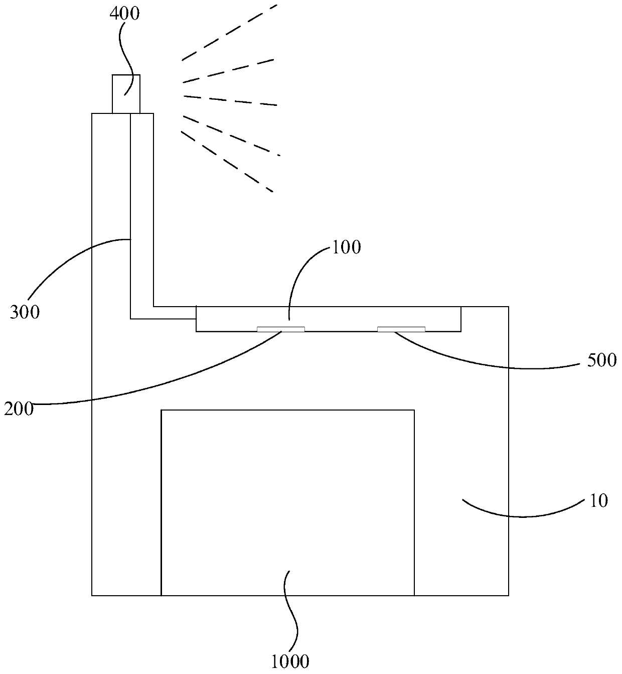
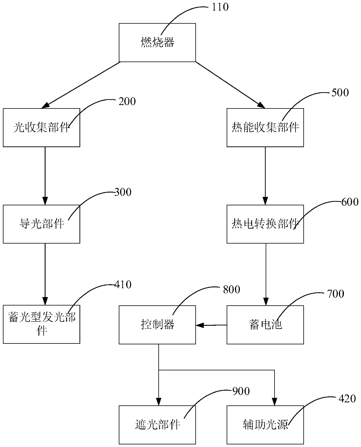
The invention relates to a kitchen appliance. The kitchen appliance comprises a stove, an energy collecting part and an energy utilization part; the stove comprises a combustor; the combustor can generate flame when working; the energy collecting part is arranged on the stove and is used for collecting the energy emitted from the flame; and the energy utilization part is connected with the energycollecting part and can utilize the energy emitted from the flame. According to the kitchen appliance, the energy of the flame generated by the combustor can be collected through the energy collectingpart and then utilized to the energy utilization part, such that the kitchen appliance can make full use of the energy when the gas is combusted and can effectively improve the energy utilization rate.

Description

technical field [0001] The invention relates to the technical field of cooking equipment, in particular to kitchen utensils. Background technique [0002] With the development of society, various hotels, restaurants, factory canteens, school canteens and family kitchens and other places in life now need to use stoves. At present, the stoves on the market mainly use gas to heat the pot. During the use of the stove, the light and heat generated by the combustion of the gas will radiate in all directions. Usually, there will be a large energy loss and the energy utilization rate is low. . Contents of the invention [0003] Based on this, it is necessary to provide a kitchen appliance with high energy efficiency. [0004] A kitchen utensil, comprising: a cooker, the cooker includes a burner, and the burner can generate flames when it is in operation; an energy collecting part, the energy collecting part is arranged on the cooker, and is used to collect the flames energy; an...

Claims


Application Information

Patent Timeline
IPC IPC(8): F24C3/00F24C15/34F21K2/00F21V1/14F21V17/10F21V8/00F21V33/00H02N11/00F21Y113/20
CPCF21K2/00F21V1/14F21V17/10F21V33/0004F21V2200/00F21Y2113/20F24C3/008F24C15/34H02N11/00
Inventor 梁荣王宏徐成梁浩欢张皓坤马雪玲
Owner GREE ELECTRIC APPLIANCES INC
Why Eureka
Try Eureka