Eureka AIR delivers breakthrough ideas for toughest innovation challenges, trusted by R&D personnel around the world.

Method for controlling three-valve heat exchanger through flow speed difference

A technology of controller and flow rate difference, which is applied in the direction of indirect heat exchanger, heat exchanger type, heat exchanger shell, etc., can solve the problems of low intelligence and poor vibration heat transfer effect, and achieve accurate and good results The effect of descaling and heat exchange effect

Inactive Publication Date: 2020-07-14
QINGDAO UNIV OF SCI & TECH
View PDF0 Cites 3 Cited by
  • Summary
  • Abstract
  • Description
  • Claims
  • Application Information

AI Technical Summary

Problems solved by technology

[0009] In the previous application, a shell-and-tube heat exchanger with heat exchange of four fluids has been developed, but the above-mentioned shell-and-tube heat exchanger is controlled according to the cycle, resulting in poor vibration heat exchange effect and partial intelligence. Low

Method used


Image

  • Method for controlling three-valve heat exchanger through flow speed difference
  • Method for controlling three-valve heat exchanger through flow speed difference
  • Method for controlling three-valve heat exchanger through flow speed difference

Examples


Embodiment Construction

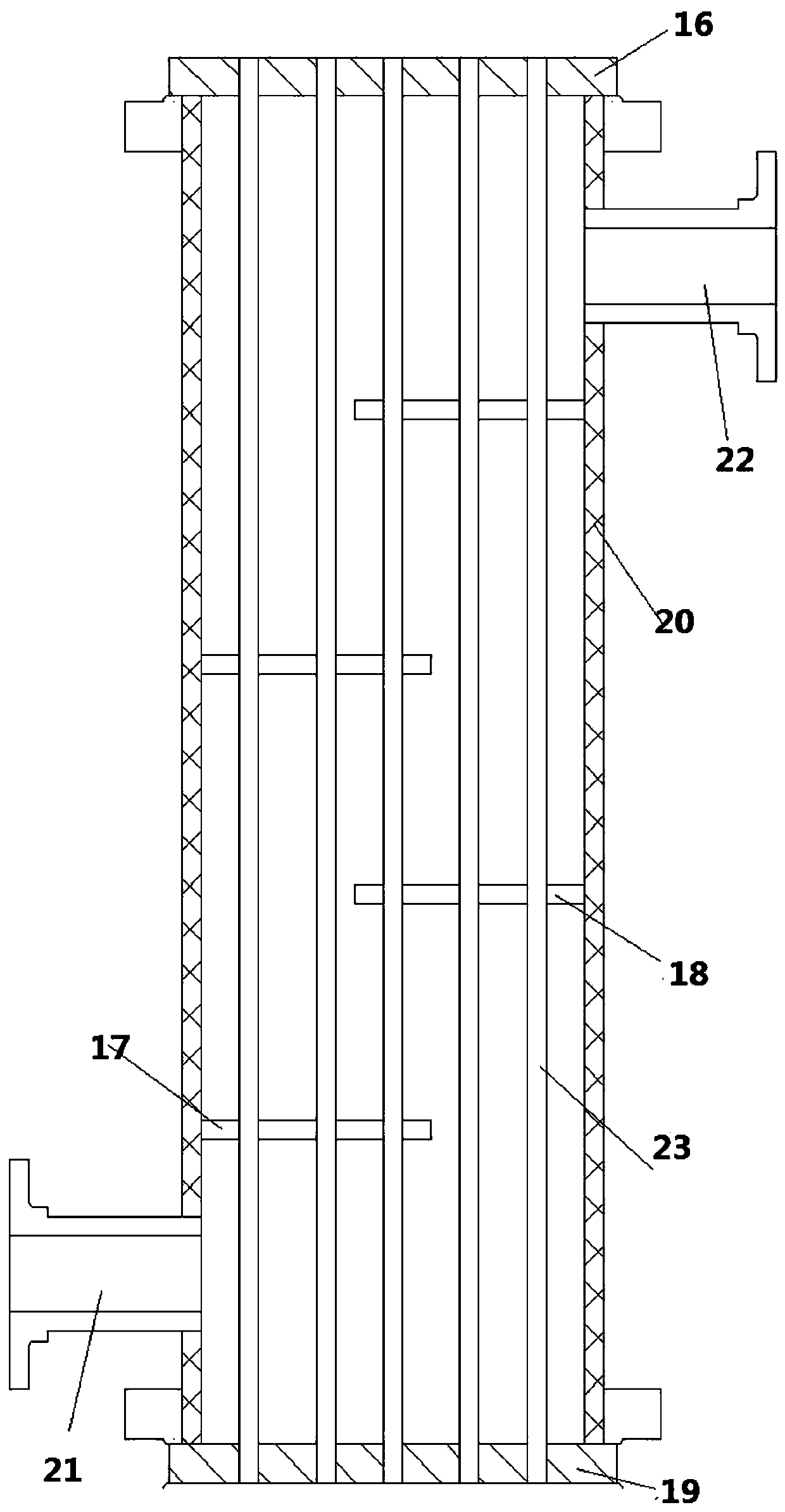
[0035] A shell-and-tube heat exchanger, such as figure 1 As shown, the shell-and-tube heat exchanger includes a shell 20, a heat exchange component 23, a shell side inlet connection 21 and a shell side outlet connection 22; the heat exchange component 23 is arranged in the shell 20, and the heat exchange component It is fixedly connected to the front tube sheet 16 and the rear tube sheet 19; the shell-side inlet connecting pipe 21 and the shell-side outlet connecting pipe 22 are both arranged on the shell 20; the fluid enters from the shell-side inlet connecting pipe 21 and passes through the heat exchange components. For heat exchange, take over the outlet pipe 22 on the shell side to go out.

[0036] Preferably, the heat exchange component extends along the vertical direction. The heat exchangers are arranged vertically.

[0037] Preferably, the shell-side fluid is a gas. The gas is preferably air, or carbon dioxide gas.

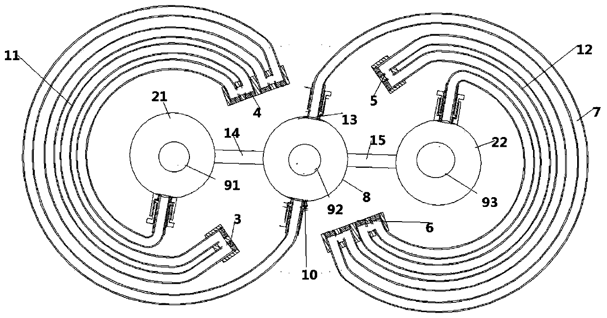
[0038] figure 2A top view of the heat exchange...


PUM


Abstract

The invention provides a method for controlling a three-valve heat exchanger through the flow speed difference. A first valve, a second valve and a third valve are arranged at inlets of a first heat exchange pipe, a second heat exchange pipe and a third heat exchange pipe correspondingly. A speed induction element is arranged in the free end of a pipe bundle and is used for detecting the flow speed of fluid in the free end of the pipe bundle. A flow speed sensor is in data connection with a controller. The controller extracts flow speed data according to the time sequence. Due to comparison offlow speed data of adjacent time sections, the flow speed difference or the accumulation of the flow speed difference changes of the heat exchanger is obtained, when the flow speed difference or theaccumulation of the flow speed difference changes is smaller than the threshold value, the first valve, the second valve and the third valve are controlled by the controller to be opened and closed,and whether first fluid, third fluid and second fluid conduct heat exchange or not is controlled. By means of the method, due to the fact that the speed difference or the accumulated flow speed difference changes are detected, new fluid is started to conduct alternate heat exchange, and therefore the elastic pipe bundle can be constantly driven to vibrate, and the heat exchange efficiency and thedescaling operation can be further achieved.

Description

technical field [0001] The present invention is a further improvement of the previous application, which is applied to the field of heat exchangers. The invention relates to a shell-and-tube heat exchanger, in particular to a shell-and-tube heat exchanger for gas heat exchange. Background technique [0002] The invention relates to descaling of heat exchangers, which is a new invention of shell-and-tube heat exchangers based on the research and development of Qingdao University of Science and Technology (application number 2019101874848). [0003] Shell-and-tube heat exchangers are widely used in chemical, petroleum, refrigeration, nuclear energy and power industries. Due to the worldwide energy crisis, in order to reduce energy consumption, the demand for heat exchangers in industrial production is also increasing. The quality requirements for heat exchangers are also getting higher and higher. In recent decades, although compact heat exchangers (plate, plate-fin, press-w...

Claims


Application Information

Patent Timeline
Patent Type & Authority Applications(China)
IPC IPC(8): F28D7/10F28F9/24F28F27/00F28G7/00
CPCF28D7/103F28F9/24F28F27/00F28G7/00
Inventor 王逸隆
Owner QINGDAO UNIV OF SCI & TECH
Why Eureka
Eureka Blog
Learn More