
Smoke dust removal equipment for waste incineration

A technology of waste incineration and dust removal equipment, which is applied in lighting and heating equipment, dispersed particle filtration, transportation and packaging, etc. It can solve the problems of poor dust collection effect and single dust removal structure, so as to improve the beating effect, improve the dust removal effect, and facilitate The effect of installation and removal

Inactive Publication Date: 2020-12-01
浙江万源环保机械科技有限公司
View PDF9 Cites 9 Cited by
  • Summary
  • Abstract
  • Description
  • Claims
  • Application Information

AI Technical Summary

Problems solved by technology

[0003] According to the patent document application number 201820670039.8, a waste incineration dust collection device is provided, which includes a crusher and an incinerator, and is characterized in that it also includes a belt conveyor, a dust collector, a dust suction duct, a check valve, a dryer, Hot gas nozzle, hot gas pipe, bucket elevator and dust collection hood, the dryer includes a feed cylinder, a drying cylinder, a discharge pipe and a frame, the lower end of the crusher is provided with a discharge port, the The upper part of the incinerator is provided with a feeder, the crusher is located in the pit, the left part of the belt conveyor is located below the discharge port of the crusher, and the right part of the belt conveyor is located in the dryer In the feeding barrel, the left part of the bucket elevator is set under the discharge pipe of the dryer, the right part of the bucket elevator is set in the feeder on the upper part of the incinerator, and the dust collector The cover is set above the incinerator, although the labor intensity is reduced, the degree of automation is high, and the utilization rate of heat energy is high, but the dust removal structure is single and the dust collection effect is poor.

Method used


Image

  • Smoke dust removal equipment for waste incineration
  • Smoke dust removal equipment for waste incineration
  • Smoke dust removal equipment for waste incineration

Examples


Embodiment Construction

[0022] In order to facilitate the understanding of the present invention, the present invention will be described more fully below with reference to the relevant drawings, in which several embodiments of the present invention are shown, but the present invention can be realized in different forms, and is not limited to the text described On the contrary, these embodiments are provided to make the disclosure of the present invention more thorough and comprehensive.

[0023] It should be noted that when an element is said to be "fixed on" another element, it can be directly on the other element or there can be an intervening element, and when an element is said to be "connected" to another element, it can be Directly connected to another element or possibly intervening elements at the same time, the terms "vertical," "horizontal," "left," "right," and similar expressions are used herein for purposes of illustration only.

[0024] Unless otherwise defined, all technical and scien...


PUM


Abstract

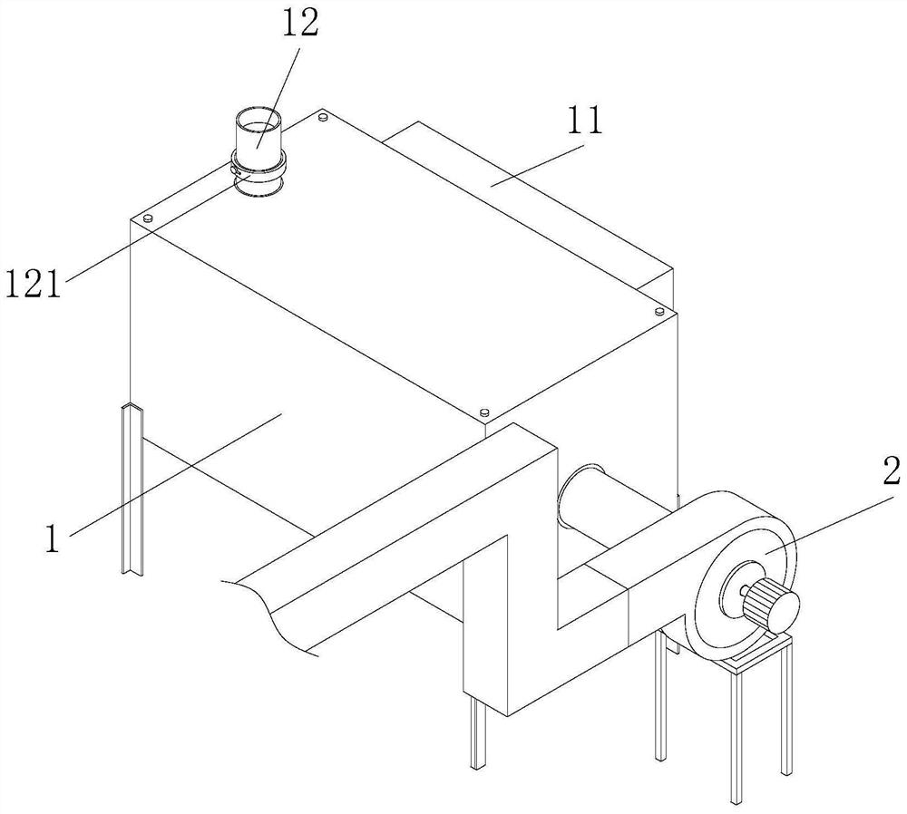
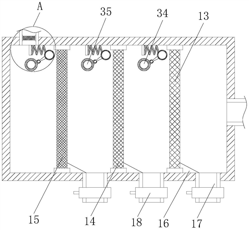
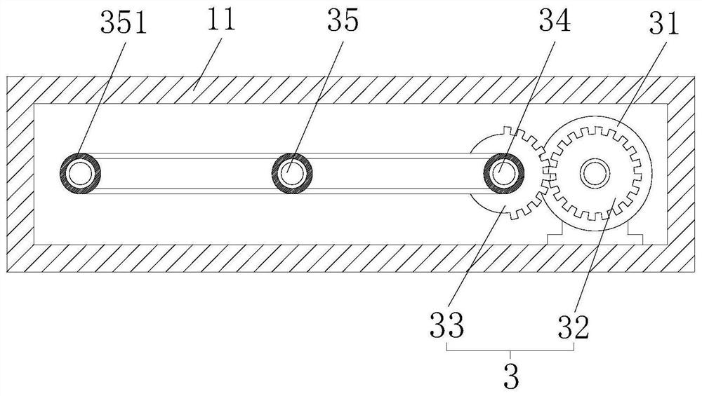
The invention provides smoke dust removal equipment for waste incineration. The smoke dust removal equipment comprises a dust collecting box, a dust suction fan is arranged in front of the dust collection box, a first filter screen, a second filter screen and a third filter screen are arranged on the inner side of the dust collecting box, a protective cover is arranged on one side of the dust collecting box, an anti-blocking assembly is arranged on the inner side of the protective cover, the anti-blocking assembly comprises a driving motor, a straight gear is arranged on an output shaft of thedriving motor, one side of the straight gear is engaged with a sector gear, one side of the sector gear is provided with a first rotating shaft and two second rotating shafts, one end of the first rotating shaft and one ends of the second rotating shafts are each provided with a connecting block, one side of each connecting block is provided with a connecting rod, and one end of each connecting rod is provided with a beating ball. Through the dust suction fan, the first filter screen, the second filter screen and the third filter screen, multi-stage filtration of dusty air is achieved, vibration of the filter screens is achieved through the anti-blocking assembly, the filter screens can be effectively prevented from being blocked, and the dust removal effect is improved.

Description

technical field [0001] The invention mainly relates to the technical field of garbage incineration, in particular to a smoke and dust removal device for garbage incineration. Background technique [0002] In the existing technology, incineration is often used for garbage disposal. When incinerating garbage, a large amount of smoke and dust will be generated. If these smoke and dust are directly discharged into the air, they will pollute the environment. It is necessary to use dust removal equipment to filter the dust, and then desulfurize the gas It can only be discharged after purification treatment. [0003] According to the patent document application number 201820670039.8, a waste incineration dust collection device is provided, which includes a crusher and an incinerator, and is characterized in that it also includes a belt conveyor, a dust collector, a dust suction duct, a check valve, a dryer, Hot gas nozzle, hot gas pipe, bucket elevator and dust collection hood, th...

Claims


Application Information

Patent Timeline
Patent Type & Authority Applications(China)
IPC IPC(8): B01D46/12F23J15/02B01D46/00
CPCB01D46/12B01D46/0005F23J15/025B01D46/0002F23J2217/10B01D46/76
Inventor 汤炳
Owner 浙江万源环保机械科技有限公司
Learn More