Eureka AIR delivers breakthrough ideas for toughest innovation challenges, trusted by R&D personnel around the world.

Layered grinding equipment

A grinding equipment and grinding technology, applied in solid separation, sieves, grids, etc., can solve problems such as limitations of applicability and practicability, affecting the normal use of materials, time-consuming and laborious re-grinding, etc., to save manpower and Material resources, avoid heavy grinding again, and improve efficiency

Active Publication Date: 2016-09-07
陕西阿姑农业发展有限公司
View PDF8 Cites 10 Cited by
  • Summary
  • Abstract
  • Description
  • Claims
  • Application Information

AI Technical Summary

Problems solved by technology

[0002] In the processing of some products, grinding is generally required. The existing grinding equipment is prone to insufficient grinding during the grinding process, so there will still be unground particles in the ground product. Products, which will affect the normal use of materials to a certain extent, it not only needs to be time-consuming and laborious to grind again, which increases the cost of grinding, but also wastes manpower and material resources, so the applicability and practicability are limited

Method used


Image

  • Layered grinding equipment

Examples


Embodiment 1

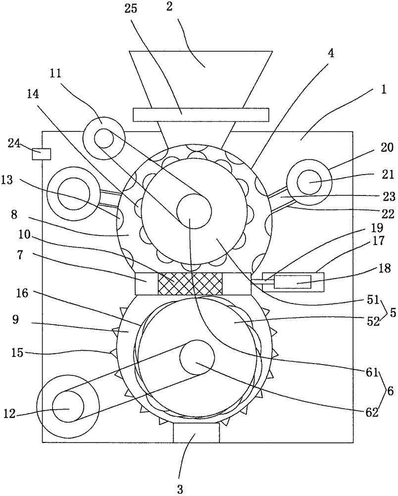
[0017] figure 1 A specific embodiment of the invention is shown in which figure 1 It is a structural schematic diagram of the present invention.

[0018] See figure 1 , a layered milling device, comprising a housing 1, on which a feed port 2, a discharge port 3 and a milling passage 4 are arranged, and a milling passage 4 is provided in the milling passage 4 The roller 5 and the rotating shaft 6 connected with the grinding roller 5 are provided with a partition 7 in the middle of the grinding passage 4, and the direction of the partition 7 is consistent with the direction of the grinding passage 4. The partition plate 7 separates the grinding and pressing channel 4 into an upper grinding chamber 8 and a lower grinding chamber 9, and a screen 10 is uniformly arranged on the partition 7, and the grinding and pressing roller 5 includes an upper grinding and pressing roller 51 and a lower grinding and pressing roller. Roller 52, the rotating shaft 6 includes an upper rotating s...


PUM


Abstract

The invention discloses layered grinding equipment. The layered grinding equipment comprises a shell body which is provided with a feeding inlet, a discharging outlet and a grinding and pressing channel. The grinding and pressing channel is internally provided with grinding and pressing rollers, and rotating shafts connected with the grinding and pressing rollers, and a partition plate is arranged in the middle of the grinding and pressing channel. The direction of the partition plate is the same as that of the grinding and pressing channel. The grinding and pressing channel is divided into an upper grinding cavity and a lower grinding cavity through the partition plate. Screen nets are uniformly arranged on the partition plate. The grinding and pressing rollers comprise the upper-layer grinding and pressing roller and the lower-layer grinding and pressing roller. The rotating shafts comprise the upper-layer rotating shaft and the lower-layer rotating shaft. The feeding inlet communicates with the upper grinding cavity. The discharging outlet communicates with the lower grinding cavity. The shell body is provided with an upper driving motor and a lower driving motor. According to the layered grinding equipment, the structure is simple, operation is convenient, grinding is conducted through the up-down two-layer structure, and the situation of insufficient grinding can be effectively avoided; accordingly, regrinding is avoided, human and material resources are saved, and the machining cost is greatly reduced; and the using stability is good, the applicability is high, and the practicality is good.

Description

technical field [0001] The invention belongs to the technical field of processing equipment, and in particular relates to a layered grinding equipment. Background technique [0002] In the processing of some products, grinding is generally required. The existing grinding equipment is prone to insufficient grinding during the grinding process, so there will still be unground particles in the ground product. The product will affect the normal use of the material to a certain extent. It not only needs time-consuming and laborious grinding again, which increases the cost of grinding, but also wastes manpower and material resources, so the applicability and practicality are limited. Contents of the invention [0003] In order to solve the above technical problems, the present invention provides a layered grinding equipment with simple structure, good stability in use and effective improvement of grinding effect. [0004] The technical solution to realize the purpose of the pre...

Claims


Application Information

Patent Timeline
Patent Type & Authority Applications(China)
IPC IPC(8): B02C4/10B02C4/28B02C4/42B02C4/30B07B1/50B02C23/16B02C21/00
CPCB02C4/10B02C4/28B02C4/30B02C4/42B02C21/00B02C23/16B02C2023/165B07B1/50
Inventor 王恒标
Owner 陕西阿姑农业发展有限公司
Why Eureka
Eureka Blog
Learn More