Attachment magnetic pole for lifting magnet, lifting magnet having magnetic pole for hoisting steel material, method for conveying steel material, and method for manufacturing steel plate

A technology for lifting electromagnets and magnetic poles, which is applied in the direction of electromagnets, electromagnets, magnetic cores/yokes, etc.

Active Publication Date: 2020-07-14
JFE STEEL CORP
View PDF9 Cites 0 Cited by
  • Summary
  • Abstract
  • Description
  • Claims
  • Application Information

AI Technical Summary

Problems solved by technology

Therefore, depending on the skill of the operator who operates the crane, it is necessary to re-operate several times, resulting in a significant drop in work efficiency.
In addition, the above-mentioned work of adjusting the number of sheets to be sucked has become a big obstacle to crane automation.

Method used


Image

  • Attachment magnetic pole for lifting magnet, lifting magnet having magnetic pole for hoisting steel material, method for conveying steel material, and method for manufacturing steel plate
  • Attachment magnetic pole for lifting magnet, lifting magnet having magnetic pole for hoisting steel material, method for conveying steel material, and method for manufacturing steel plate
  • Attachment magnetic pole for lifting magnet, lifting magnet having magnetic pole for hoisting steel material, method for conveying steel material, and method for manufacturing steel plate

Examples


no. 1 approach >

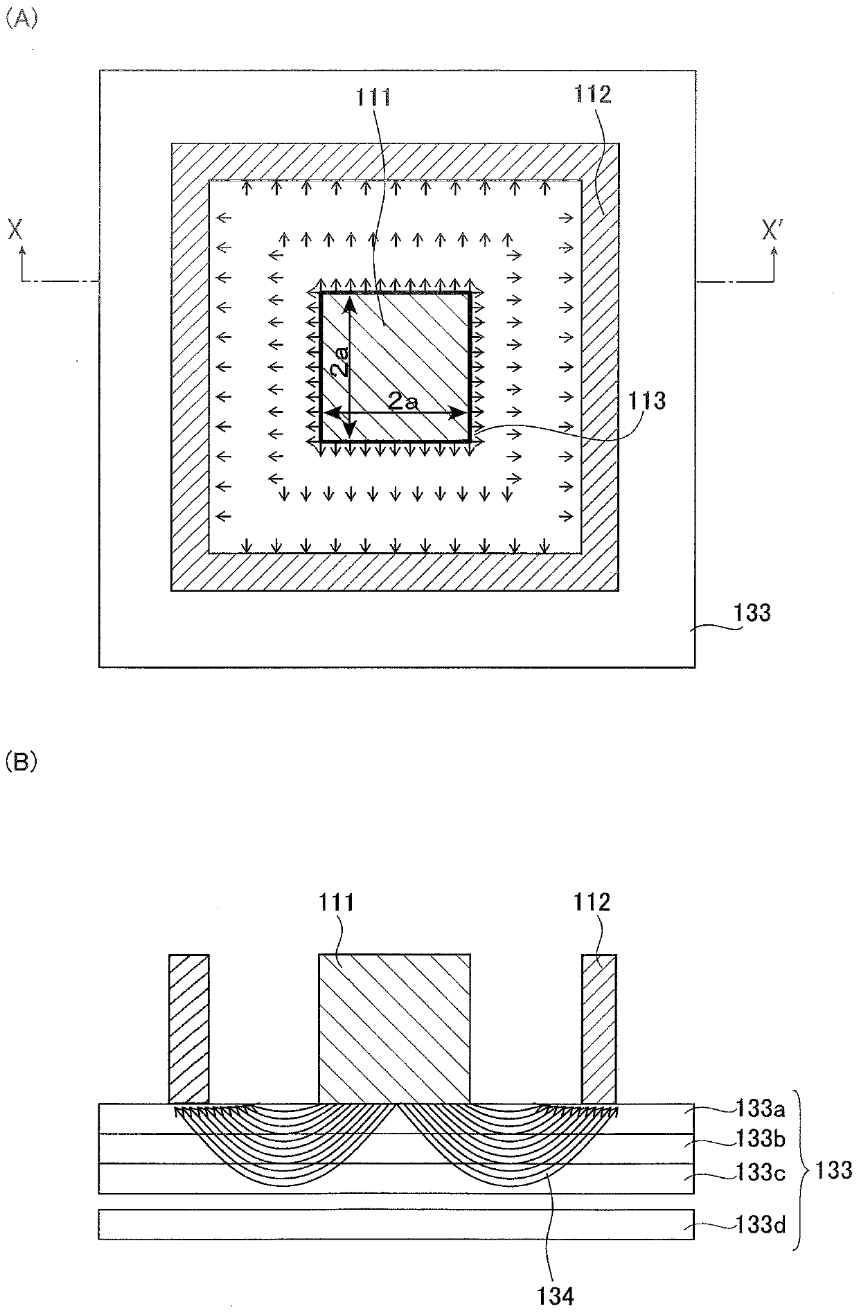
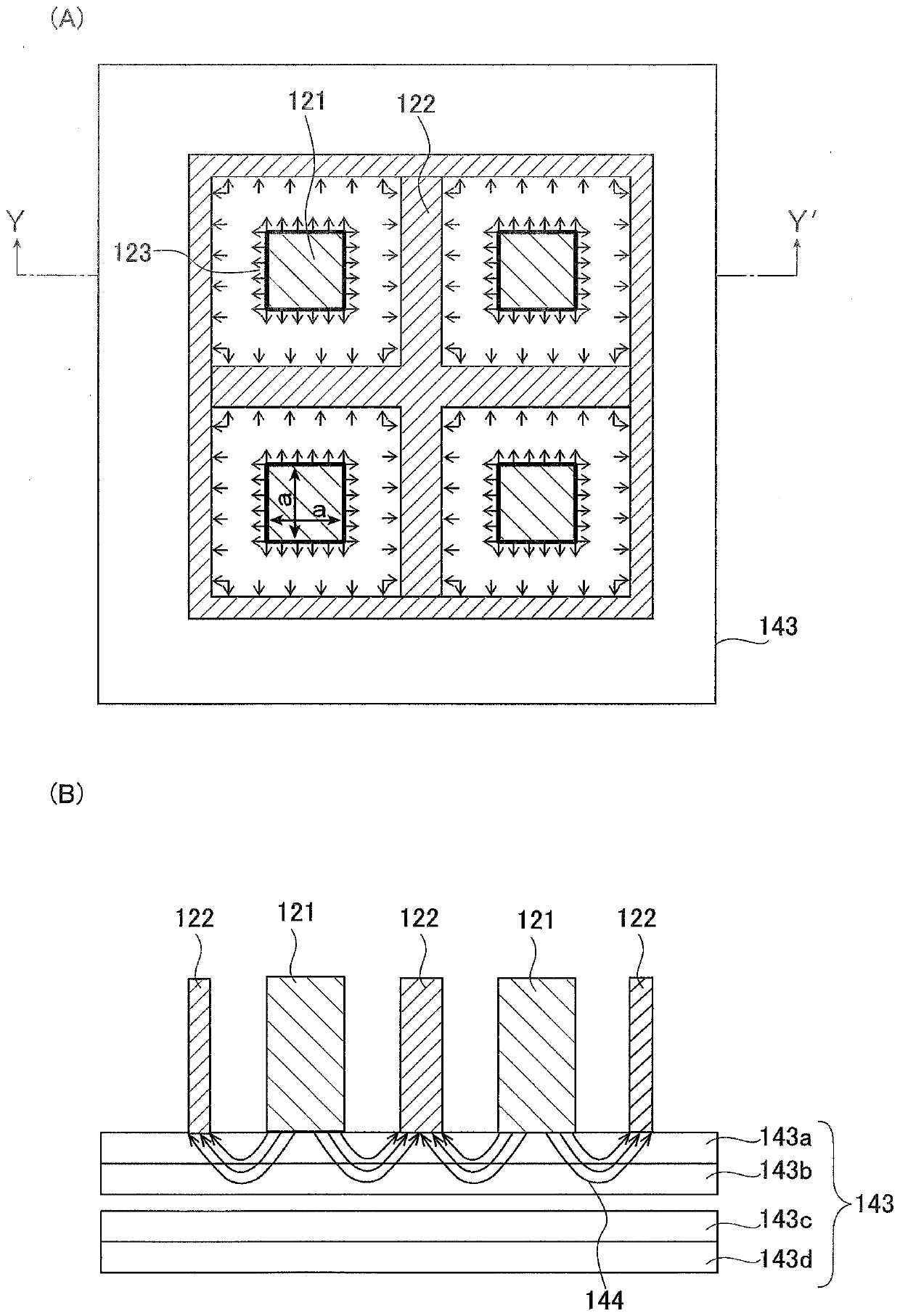
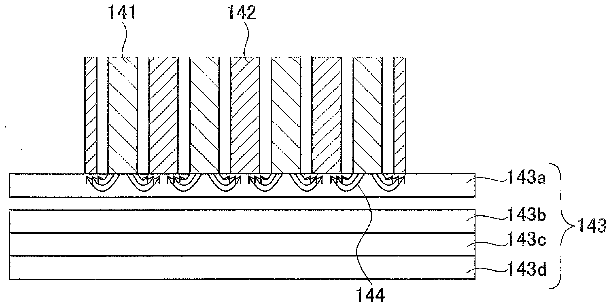
[0075] The mounting magnetic pole for a lifting electromagnet of the first embodiment is a mounting magnetic pole for a lifting electromagnet that lifts and transports a steel material by magnetic force, and has a magnetic pole that is in contact with the iron core of the lifting electromagnet and has a The first divided magnetic poles having a branched structure and the second divided magnetic poles having a branched structure contacting the yoke of the lifting electromagnet are arranged alternately. In addition, the size of the above-mentioned first divided magnetic pole may satisfy Expression (1) described later. Also, the interval between the alternately arranged first and second divided magnetic poles may be set to be 30 mm or less. In addition, the plate thicknesses of the above-mentioned first and second divided magnetic poles may be set to be 20 mm or less, respectively.

[0076] The lifting electromagnet with magnetic poles for lifting steel materials according to th...

no. 2 approach >

[0106] In addition to the basic structure of the above-mentioned first embodiment, the lifting electromagnet with the mounting magnetic pole for the lifting electromagnet and the lifting electromagnet with the magnetic pole for lifting the steel material of the second embodiment further have at least one movable magnetic pole, and The fixed magnetic pole is in the area adjacent to the movable magnetic pole and on the surface that is in contact with the steel material. In addition, the above-mentioned movable magnetic pole may be set as a movable type. In addition, the dimensions of the above-mentioned fixed magnetic poles may satisfy Expression (2) described later.

[0107] In the second embodiment of the present invention, as mentioned above, a lifting electromagnet with a magnetic pole is used to control the number of sheets of steel to be lifted such as only one piece of steel or only the target number of sheets (such as 2 ~3 sheets). The inventors of the present inventio...

Embodiment 1

[0165] Figure 7 It is a schematic diagram explaining the schematic structure of the attachment magnetic pole for lifting electromagnets in 1st Embodiment of this invention used in Example 1. Figure 7 (A) shows a plan view of the mounting pole for the lifting electromagnet viewed from below, Figure 7 (B) shown in Figure 7 D-D' line sectional view in (A), Figure 7 (C) shown in Figure 7 E-E' line sectional view in (A).

[0166] In Embodiment 1, as an example of the present invention, a lifting electromagnet (not shown) having an inner pole with a diameter of 150mm, a thickness of 60mm, and an outer pole with a size of 500mm×500mm is used. Figure 7 The shown lifting electromagnet of the present invention is used to install the magnetic pole (SS400 system) Figure 6 The lifting electromagnet with magnetic poles shown is used to carry out the lifting test of the steel plate. The thickness of the magnetic pole was set to 10 mm, and a gap of 20 mm was provided between the...


PUM

PropertyMeasurementUnit
thicknessaaaaaaaaaa
saturation flux densityaaaaaaaaaa
thicknessaaaaaaaaaa

Abstract

Provided are an attachment magnetic pole for a lifting magnet with which it is possible to acquire one or a desired number of plates of a steel material, a lifting magnet, a method for conveying a steel material, and a method for manufacturing a steel plate. The present invention is an attachment magnetic pole for a lifting magnet, the attachment magnetic pole being used in a lifting magnet that hoists and transports a steel material through use of magnetic force, wherein the attachment magnetic pole has a first divided magnetic pole that has a branching structure and is in contact with an iron core of the lifting magnet, and a second divided magnetic pole that has a branching structure and is in contact with a yoke of the lifting magnet; and the first and second divided magnetic poles aredisposed in an alternating manner.

Description

technical field [0001] The present invention relates to a mounting magnetic pole for a lifting electromagnet used for hoisting and transporting steel materials in ironworks, steel plate processing plants, etc., a lifting electromagnet with a magnetic pole for lifting steel materials, a method of transporting steel materials, and manufacturing of steel plates method. Background technique [0002] Lifting and conveying of steel in the heavy plate factory of the ironworks. The process in the heavy plate factory is roughly divided into a rolling process of rolling a block-shaped steel material to a desired thickness to form a steel plate, cutting to the shipping size, removing burrs at the end, and repairing surface defects. , Inspection of internal defects and other finishing processes. From the point of view of the restriction of the storage place, the steel plates waiting for the finishing process and the steel plates waiting for shipment after the finishing process are sto...

Claims


Application Information

Patent Timeline
Patent Type & Authority Applications(China)
IPC IPC(8): B66C1/06
CPCB66C1/04H01F7/206H01F3/10B66C1/06H01F7/13H01F7/18
Inventor 高木勇辉小林正树四辻淳一
Owner JFE STEEL CORP
Why Eureka
Try Eureka