Pantograph device with jet device

A pantograph and device technology, applied in the field of pantograph-catenary system, can solve problems such as discomfort of people in the vehicle, potential safety hazards, aerodynamic noise, etc.

Active Publication Date: 2021-05-25
SOUTHWEST JIAOTONG UNIV
View PDF7 Cites 0 Cited by
  • Summary
  • Abstract
  • Description
  • Claims
  • Application Information

AI Technical Summary

Problems solved by technology

[0002] The pantograph-catenary system is the power source for train operation, but with the rapid increase of train speed, the hazards of aerodynamic noise and pantograph-catenary offline are becoming more and more significant
First of all, because the airflow in motion is affected by the uneven position of the train surface, the collision between the two will cause severe far-field air pulsation pressure field changes, which will cause aerodynamic noise problems, and the sound pressure level will also increase by 6 to 8 times with the speed of the train. The increase of the square ratio will cause extreme discomfort to the people in the train, and when the train is running at high speed, the pantograph will slide longitudinally due to various reasons, which will lead to the offline of the pantograph and catenary, posing a great safety hazard

Method used


Image

  • Pantograph device with jet device
  • Pantograph device with jet device
  • Pantograph device with jet device

Examples


Embodiment 1

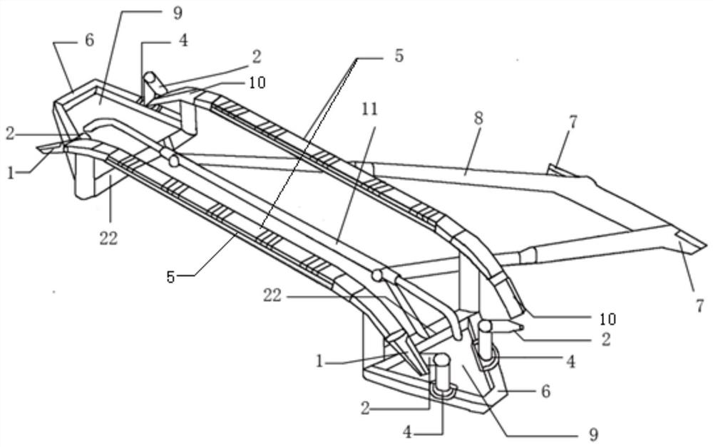
[0040] Such as figure 1 As shown, the present invention provides a pantograph device with a jet device, including a gas jet device 9, a bow bracket 22, an upper frame 8 and an empennage hinge seat 7;

[0041] The gas jet device is arranged on both sides of the bow bracket 22, the front and rear ends of the top of the bow bracket 22 are provided with contact slides 5, and the two sides of the contact slide 5 are provided with bow angles, and the bow bracket 22 is connected to the empennage hinge seat 7 through the upper frame 8 .

[0042] In the embodiment of the present invention, such as figure 1 As shown, the plane formed by the fixed connection of the two tripod brackets is 0-60° to the plane fixed by the bow head bracket;

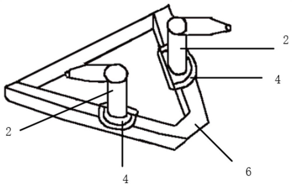
[0043] In the embodiment of the present invention, such as figure 2 As shown, the gas jet device includes a bow bracket 22, a tripod bracket 6, a gas jet generator 2 and a vertically rotating stepper motor 4;

[0044] In the embodiment of the prese...


PUM


Abstract

The invention discloses a pantograph device with a jet device. The pantograph device comprises a triangular support, a gas jet generator, a vertical rotation stepping motor, a front wing type sliding plate pantograph angle, a rear trapezoid type sliding plate pantograph angle, an upper frame, a pantograph head support, a balance rod and a tail wing type hinge base. According to the invention, two pairs of reverse and forward gas jet generators are used for respectively draining gas around the front wing type sliding plate arch angle and the rear trapezoid type sliding plate arch angle, and the collision between the gas and the two sliding plates is reduced by matching with the improved front wing type sliding plate arch angle and the improved rear trapezoid type sliding plate arch angle; the air lifting force of the front sliding plate is increased by guiding air, the air vortex and the air resistance at the bow corner of the rear sliding plate are reduced, finally, the tail wing type hinge base is combined, collision between the air and the pantograph is effectively relieved, noise reduction of the pantograph is achieved, the offline rate of a pantograph net is reduced, and safe and stable operation of a high-speed railway is guaranteed.

Description

technical field [0001] The invention relates to the field of pantograph-catenary systems, in particular to a pantograph device with jet devices. Background technique [0002] The pantograph-catenary system is the power source for train operation, but with the rapid increase of train speed, the hazards of aerodynamic noise and pantograph-catenary offline are becoming more and more significant. First of all, because the airflow in motion is affected by the uneven position of the train surface, the collision between the two will cause severe far-field air pulsation pressure field changes, which will cause aerodynamic noise problems, and the sound pressure level will also increase by 6 to 8 times with the speed of the train. The increase of the square ratio will cause extreme discomfort to the people in the train, and when the train is running at high speed, the pantograph will slide longitudinally due to various reasons, which will lead to the off-line of the pantograph and the...

Claims


Application Information

Patent Timeline
Patent Type & Authority Applications(China)
IPC IPC(8): B60L5/20
CPCB60L5/205B60L5/20
Inventor 杨泽锋陈星向宇李箫波魏文赋阴国锋高国强吴广宁
Owner SOUTHWEST JIAOTONG UNIV
Why Eureka
Try Eureka