Cross-occlusion proximal femoral nail

A proximal femur and intramedullary nailing technology, which is applied in the field of medical devices, can solve the problems of reducing anti-rotational stability, increasing the stress at the junction of the head and neck, and retracting the nail, so as to reduce the risk of fracture and increase the effect of anti-rotational stability

Pending Publication Date: 2020-07-17
吴丹凯
View PDF0 Cites 1 Cited by
  • Summary
  • Abstract
  • Description
  • Claims
  • Application Information

AI Technical Summary

Problems solved by technology

Later, many doctors found some problems after long-term follow-up: the nail tip of a single tension nail is prone to stress concentration, and its anti-rotation ability is poor. There is a risk of nail withdrawal and nail cutting out of the femoral head, which may easily cause coxa varus and limb shortening. Deformity and other complications, so it is not suitable for osteoporotic patients and obese patients. In order to overcome these shortcomings, PFN (proximal femoral nail) appeared
However, InterTan’s centralized placement of the two scattered PFN screws also has many disadvantages: ①Reduces the anti-rotational stability; ②Increases the stress at the junction of the head and neck, which is easy to cause stress fatigue fracture; ③There is only pressure support, lack of tension Support, there is still the risk of the screw cutting out the femoral head; ④The bone loss in the femoral head is relatively large, especially concentrated in the lower third of the femoral head, so there are unstable factors after the internal fixation is removed; ⑤InterTan is not suitable for short stature patient

Method used


Image

  • Cross-occlusion proximal femoral nail
  • Cross-occlusion proximal femoral nail
  • Cross-occlusion proximal femoral nail

Examples


Embodiment Construction

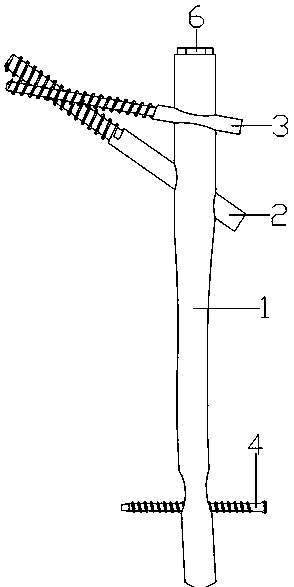
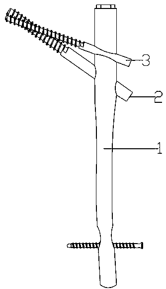
[0025] see Figure 1 to Figure 8 As shown, a proximal femoral intramedullary nail with cross occlusion includes a main nail 1, a compression tension nail 2 and a tension nail 3;

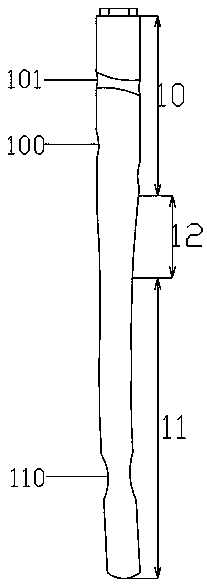
[0026] The main nail 1 includes a proximal section 10, a distal section 11 and a transition zone 12. The proximal section 10 and the distal section 11 are integrally connected through the transition zone 12. corner of

[0027] The near section 10 of the main nail 1 is provided with a first nail hole 100 and a second nail hole 101, the first nail hole 100 is located at the distal end of the main nail 1 near section 10, and the second nail hole 101 is located at the end of the main nail 10. 1 The middle part of the proximal section 10 is forward, the first nail hole 100 is placed into the compression tension nail 2, the second nail hole 101 is placed into the tension occlusal nail 3, and the compression tension nail 2 is first The end and the head end of the tension nail 3 pass through the main nail ...


PUM


Abstract

The invention discloses a cross-occlusion proximal femoral nail. The proximal femoral nail comprises a main nail, a pressure-resistant tension nail and a tension-resistant occlusion nail, the main nail comprises a near section, a far section and a transition region, the near section and the far section are integrally connected through the transition region, a first nail hole and a second nail holeare formed in the near section of the main nail, the pressure-resistant tension nail is arranged in the first nail hole, the tension-resistant occlusion nail is arranged in the second nail hole, andthe head end of the pressure-resistant tension nail and the head end of the tension-resistant occlusion nail penetrate through the main nail and are clamped and locked through threads on the outer surfaces. The proximal femoral nail is used for reconstructing the intertrochanteric part of the proximal femoral end, the pressure-resistant tension nail and the tension-resistant occlusion nail are crossly occluded on the femoral head and the neck to form a ward triangle stable bionic support structure, the rotation stability of the intramedullary nail is improved, the pressure-resistant tension nail forms a pressure-resistant support structure, the tension-resistant occlusion nail forms a tension-resistant suspension structure, the compression stress at the head-neck junction of the intramedullary nail is dispersed, and the risk of breaking of the main nail and a head nail is reduced.

Description

technical field [0001] The invention relates to the technical field of medical instruments, in particular to a proximal femoral intramedullary nail with cross-occlusion. Background technique [0002] Intertrochanteric fractures, also known as intertrochanteric fractures, refer to fractures at the base of the femoral neck to above the level of the lesser trochanter. Intertrochanteric fracture is a clinically common type of fracture, and it is more common in the elderly, especially in patients with medical chronic diseases or osteoporosis. With the deepening of the aging population in my country, the incidence of intertrochanteric fractures is also showing an increasing trend year by year, accounting for 33%-50% of all hip fracture patients. If patients with intertrochanteric fractures fail to receive timely and effective treatment and intervention, a variety of structural dysfunctions may occur, such as limb shortening, coxa varus, hip joint dysfunction, etc., causing seriou...

Claims


Application Information

Patent Timeline
IPC IPC(8): A61B17/72A61B17/76
CPCA61B17/725A61B17/744A61B2017/564
Inventor 任广凯吴丹凯彭传刚
Owner 吴丹凯
Why Eureka
Try Eureka