
Simple orthodontic indirect bonding bracket transfer device in clinical diagnosis room

A transfer device and a simple technology, applied in the field of orthodontic correction, can solve the problems that the upper and lower molds are easy to form a block, the upper and lower molds are not easy to dismantle and change proofreading again, and cannot be displayed visually, so as to achieve the effect of fast connection and installation and avoiding radial rotation

Inactive Publication Date: 2020-07-17
马莉莉
View PDF0 Cites 1 Cited by
  • Summary
  • Abstract
  • Description
  • Claims
  • Application Information

AI Technical Summary

Problems solved by technology

[0004] The present invention proposes a simple orthodontic indirect bonding bracket transfer device in the clinical clinic, which solves the problem of the traditional orthodontic indirect bonding bracket transfer device when connecting the bracket to the dental mold The rotation and fixed connection between the upper and lower molds of the mold, when the technicians are bonding, it is easy to form a block between the upper and lower molds. If a single upper and lower mold is bonded and then connected, it is not easy to remove and change the proofreading between the upper and lower molds again. The upper and lower molds need to be opened when inspecting the brackets on the inner side of the dental mold, which cannot be displayed visually

Method used


Image

  • Simple orthodontic indirect bonding bracket transfer device in clinical diagnosis room
  • Simple orthodontic indirect bonding bracket transfer device in clinical diagnosis room

Examples


Embodiment Construction

[0021] The following will clearly and completely describe the technical solutions in the embodiments of the present invention with reference to the accompanying drawings in the embodiments of the present invention. Obviously, the described embodiments are only some, not all, embodiments of the present invention.

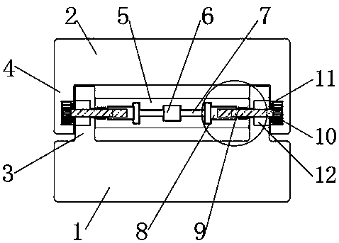
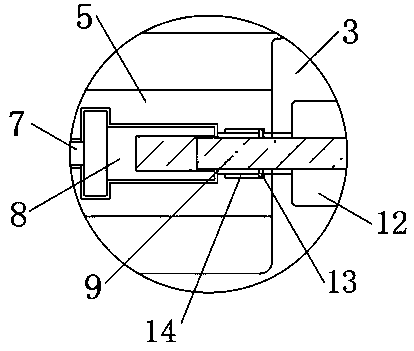
[0022] refer to Figure 1-2 , a simple orthodontic indirect bonding bracket transfer device in a clinical clinic, including a first transfer dental model 1, a second transfer dental model 2 and a tube bridge 5, the inner middle part of the tube bridge 5 is rotatably connected with a cylindrical knob 6. Both ends of the cylindrical knob 6 are fixedly connected with a rotary rod 7, and one end of the two rotary rods 7 is fixedly connected with a threaded barrel 8, and one end of the two threaded barrels 8 is threaded and socketed with a thread Rod 9, one end of the two threaded rods 9 is fixedly connected with a spline block 10.

[0023] In this embodiment, a pair of ...


PUM


Abstract

The invention discloses a simple orthodontic indirect bonding bracket transfer device in a clinical diagnosis room, and relates to the technical field of orthodontic correction. Aiming at the problemsthat: according to traditional orthodontic indirect bonding bracket transferring devices, when a bracket is transferred and connected to a dental cast, an upper die and a lower die easily act as a block and are not easy to disassemble, change and calibrate again, the upper die and the lower die need to be opened when the bracket on the inner side of the dental cast is inspected, and thus the bracket cannot be visually displayed, the invention provides the following scheme. The device comprises a first transfer dental cast, a second transfer dental cast and a cylinder bridge, and a cylindricalknob is rotatably connected to the inner middle of the cylinder bridge. According to the invention, through the design of the cylinder bridge and related structures in the cylinder bridge, the connecting installation and rapid disassembly between the first transfer dental cast and the second transfer dental cast are conveniently realized, the first transfer dental cast and the second transfer dental cast can be rotationally adjusted to be in an open state, the first transfer dental cast and the second transfer dental cast in the open state are fixed, and the bracket bonding effect can be conveniently and visually displayed.

Description

technical field [0001] The invention relates to the technical field of tooth orthodontic correction, in particular to a simple orthodontic indirect bonding bracket transfer device in a clinical clinic. Background technique [0002] Orthodontics is what we call orthodontics, which is to correct teeth, remove malocclusion and deformity. Brackets are an important part of fixed orthodontic technology. Teeth exert various types of orthodontic force. Brackets are made of stainless steel, bioceramic or composite resin, and their main function is to fix the arch wire, so that the arch wire can play a better role and transmit the orthodontic force, so as to control the three-dimensional movement of the teeth and achieve the purpose of orthodontic treatment. When the brackets are bonded to the human oral cavity, the brackets need to be bonded to the dental model and adjusted before being transferred to the human oral cavity. The dental models are generally divided into upper and lowe...

Claims


Application Information

Patent Timeline
Patent Type & Authority Applications(China)
IPC IPC(8): A61C7/14
CPCA61C7/146A61C7/16
Inventor 马莉莉
Owner 马莉莉
Learn More