
Crankshaft rotary type high-speed bidirectional oscillation stirring robot

A crankshaft rotation and robot technology, which is applied to mixer accessories, shaking/oscillating/vibrating mixers, mixers, etc. The mixing effect is good, the material is fully stirred and dispersed, and the strength is guaranteed.

Pending Publication Date: 2020-07-17
绍兴权电科技有限公司
View PDF0 Cites 0 Cited by
  • Summary
  • Abstract
  • Description
  • Claims
  • Application Information

AI Technical Summary

Problems solved by technology

[0003] At present, most of the existing mixing tanks are equipped with a single rotating shaft in the mixing tank to drive the mixing blades to stir the materials in the tank; the mixing effect of this single direction is poor
For this reason, a screw-driven two-way vibratory mixing tank has also been proposed. Although the defect of one-way agitation has been improved, the two-way vibrating agitation needs to be realized by frequently changing the direction of the motor. The driving efficiency is low, and high-speed vibrating agitation cannot be realized. It is also prone to material accumulation, causing movement to be stuck, and the reliability is not high

Method used


Image

  • Crankshaft rotary type high-speed bidirectional oscillation stirring robot
  • Crankshaft rotary type high-speed bidirectional oscillation stirring robot
  • Crankshaft rotary type high-speed bidirectional oscillation stirring robot

Examples


Embodiment Construction

[0022] The present invention will be described in further detail below in conjunction with the accompanying drawings and specific embodiments, and the implementation scope of the present invention is not limited thereto.

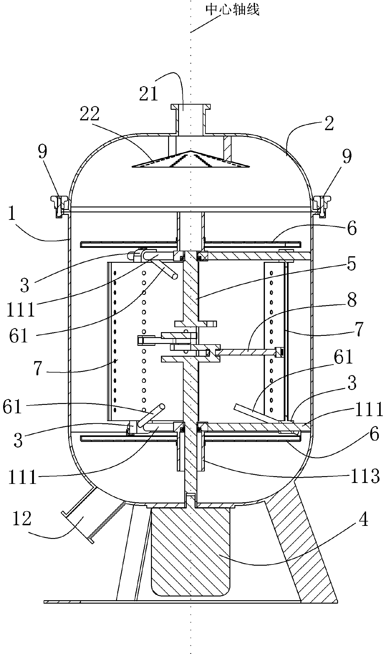
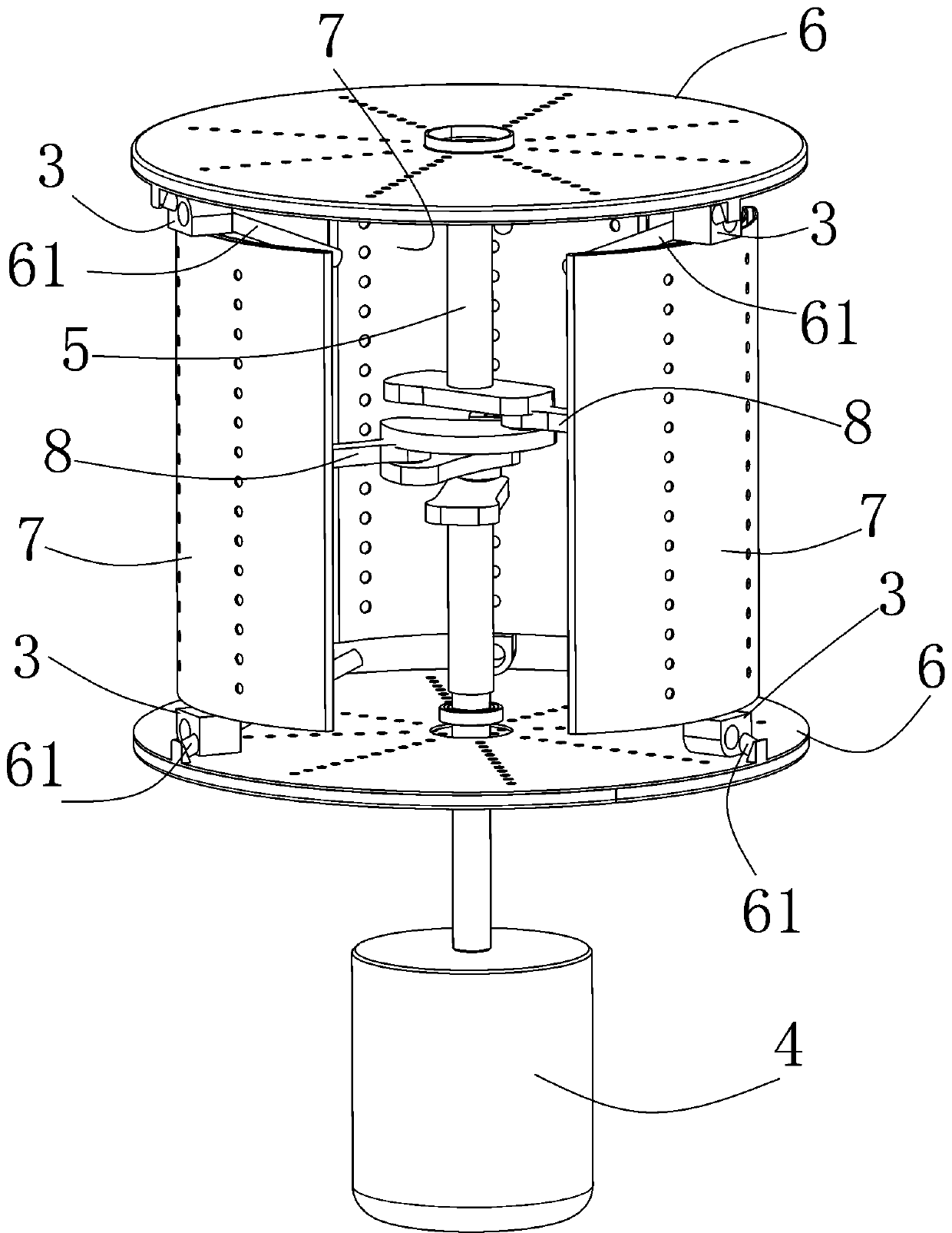
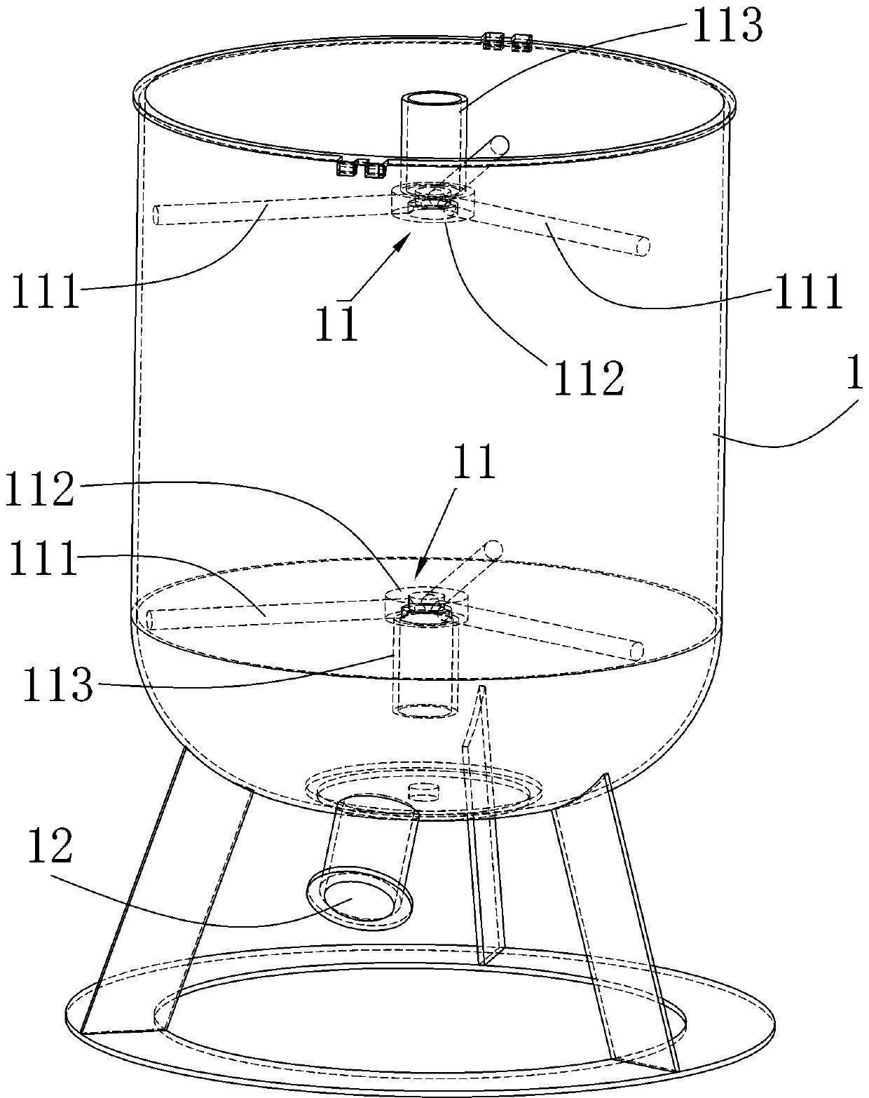
[0023] Such as Figure 1 to Figure 5 As shown, a crankshaft rotary high-speed two-way oscillating stirring robot described in this embodiment includes a tank body 1 and a top cover 2, and the top cover 2 is detachably connected to the top of the tank body 1, which is convenient for opening and maintenance operations. The top cover 2 is provided with a feeding port 21 and a feeding dispersing screen 22, the feeding dispersing screen 22 is located below the feeding port 21, and the inner wall of the tank body 1 is provided with two groups of upper and lower symmetrically arranged and The guide frame 11 that is center-radiating makes the strength of the tank body 1 higher. The guide frame 11 includes three equally spaced transverse guide rods 111 and a central ...


PUM


Abstract

The invention discloses a crankshaft rotary type high-speed bidirectional oscillation stirring robot. The robot comprises a tank body, a top cover, a driving motor, a crankshaft with three groups of cranks, two groups of symmetrical longitudinal vibrating screens and three groups of transverse vibrating screens, the top cover is detachably connected to the top end of the tank body, the top cover is provided with a feeding hole and a feeding dispersion sieve, the feeding dispersing sieve is positioned below the feeding hole, an upper guide framework and a lower guide framework are symmetricallyarranged between the inner walls of the tank body and are in a central radial shape, the guide framework comprises three transverse guide rods which are distributed at equal intervals and a central connecting part, one end of each transverse guide rod is connected to the inner wall of the tank body in the radial direction, the other end of each transverse guide rod is fixed to the central connecting part, a longitudinal guide rod is arranged on the central connecting part in the central axis direction in a protruding mode, and each transverse guide rod of each guide framework is slidably connected with a sliding guide block so that high-speed vibration stirring can be achieved, the stirring and mixing effect is better, material accumulation is not likely to happen, the clamping stagnationproblem is avoided, the strength of the tank body is guaranteed, and the reliability is high.

Description

technical field [0001] The invention relates to the technical field of stirring tanks, in particular to a crank-rotating high-speed bidirectional oscillating stirring robot. Background technique [0002] The mixing tank is a kind of equipment for stirring, mixing, blending and homogenizing materials in a closed space. It is widely used in coatings, medicine, building materials, chemicals, pigments, resins, food, scientific research and other industries. [0003] At present, most of the existing mixing tanks are equipped with a single rotating shaft in the mixing tank, which drives the stirring blades to stir the materials in the tank; the mixing effect of this single direction is poor. For this reason, a screw-driven two-way vibratory mixing tank has also been proposed. Although the defect of one-way agitation has been improved, the two-way vibration agitation needs to be realized by frequently changing the direction of the motor. The driving efficiency is low, and high-spee...

Claims


Application Information

Patent Timeline
Patent Type & Authority Applications(China)
IPC IPC(8): B01F11/00B01F15/02
CPCB01F31/00B01F31/44B01F35/71
Inventor 杨博
Owner 绍兴权电科技有限公司
Learn More