
A centering device for a heat dissipation flowmeter installed on an air duct

A centering device and flowmeter technology, which is applied in metal processing equipment, metal processing, manufacturing tools, etc., can solve the problems of increased operation risk, increased workload, heavy instrument, etc., and achieves improved operational safety, simple and convenient use, The effect of low maintenance workload

Active Publication Date: 2021-03-19
SANMEN NUCLEAR POWER CO LTD
View PDF5 Cites 0 Cited by
  • Summary
  • Abstract
  • Description
  • Claims
  • Application Information

AI Technical Summary

Problems solved by technology

However, in practical applications, there is a common problem with wafer-mounted flowmeters. Since the flowmeter probe is installed inside a closed ventilation duct, the probe is fixed through two symmetrical mounting holes with a diameter similar to that of the probe. The aperture is very small and difficult to operate. It is very difficult for the personnel to insert the probe from one side of the pipe, and to observe through the small hole and to lead out the probe from the other side and fix it. Often, blind pairing is used, which can only be completed after countless attempts. At present, there are many heat dissipation flowmeters on the market. For the integrated design, the meter is long and heavy. Using this blind operation method is time-consuming and laborious, and the installation quality cannot be guaranteed. It is easy to damage the probe during the blind pairing process, resulting in irreversible consequences; and this type of flowmeter generally Most of them are installed in mid-air, and the potential safety hazard is very high
It adds a heavy workload to daily maintenance and increases operational risks at the same time

Method used


Image

  • A centering device for a heat dissipation flowmeter installed on an air duct
  • A centering device for a heat dissipation flowmeter installed on an air duct
  • A centering device for a heat dissipation flowmeter installed on an air duct

Examples


Embodiment Construction

[0021] The present invention will be further described in detail below in conjunction with the accompanying drawings and specific embodiments.

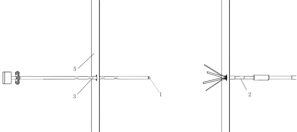
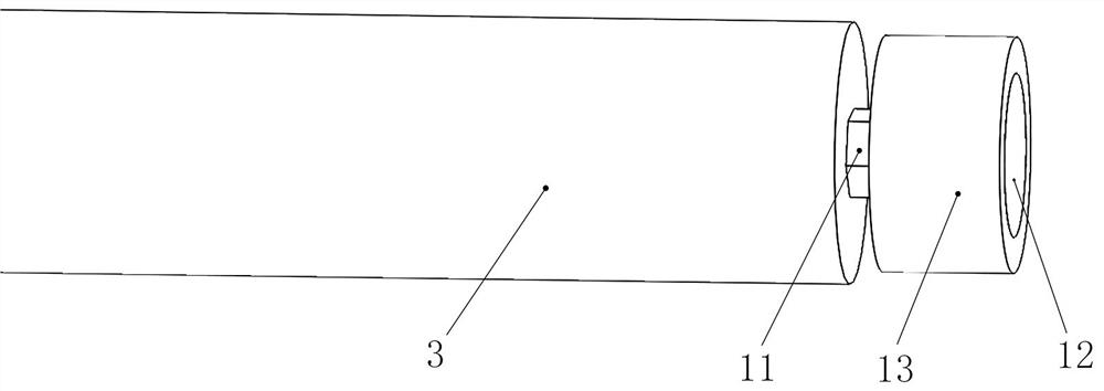
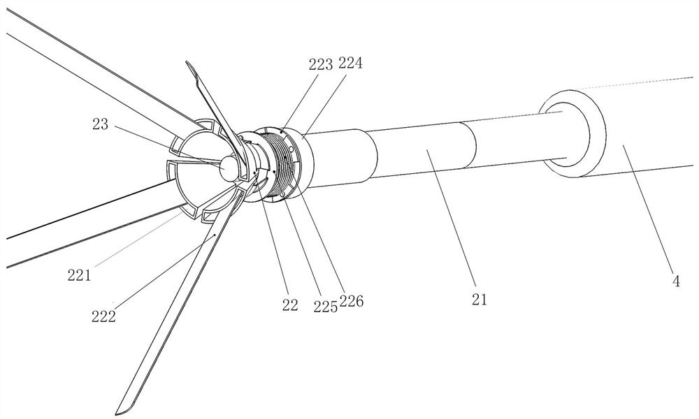
[0022] A centering device for a heat dissipation flowmeter when installed on an air duct, including a positioning device 1 and a guiding device 2, the positioning device 1 includes a fixing part 11, a fluorescent body 12 arranged on the fixing part 11 and The first magnet 13 , the guide device 2 includes a tube body 21 , a trumpet-shaped guide cylinder 22 arranged at the end of the tube body 21 , and a second magnet 23 arranged at the center of the guide cylinder 22 . Wherein, one end of the fixing member 11 is provided with a hexagonal fastening surface and an external thread for connecting to the threaded hole at the end of the probe 3 . The middle part of the end surface of the first magnet 13 is provided with a concave surface, and the phosphor 12 is disposed in the concave surface. On the one hand, the fluorescent body is placed...


PUM


Abstract

The invention discloses a centering device used when a heat dissipation type flowmeter is installed on an air pipe, and belongs to the technical field of mechanical maintenance tools. The centering device comprises a positioning device and a guiding device, the positioning device comprises a fixing piece, a fluorescent body and a first magnet, the fluorescent body and the first magnet are arrangedon the fixing piece, and the guiding device comprises a tube body, a horn-shaped guiding cylinder arranged at the end of the tube body and a second magnet arranged at the center in the guiding cylinder. The centering device is easy and convenient to operate, capable of accurately and efficiently completing centering installation of the heat dissipation type flowmeter on the air pipe, high in safety and low in cost.

Description

technical field [0001] The invention relates to the technical field of mechanical maintenance tools, in particular to a centering device when a heat radiation flowmeter is installed on an air duct. Background technique [0002] As an important part of a power plant, the ventilation system is responsible for maintaining the temperature and humidity in each room of the power plant, providing a comfortable working environment for the power plant equipment, improving the working efficiency of the equipment, reducing the failure rate, and ensuring the safe and stable operation of the power plant. In today's daily flow measurement and control of power plants, heat dissipation flow meters are widely used for measurement. Heat dissipation flow meters have the advantages of long maintenance periods, small system pressure losses, and high measurement accuracy, which are unmatched by conventional instruments. However, in practical applications, there is a common problem with wafer-moun...

Claims


Application Information

Patent Timeline
Patent Type & Authority Patents(China)
IPC IPC(8): B23P19/10
CPCB23P19/10
Inventor 周斌白俊生何凡帆金跃明张晓臣杨志业王平王超王召永白凌齐吕威张中祥余梦远杨佳儒郭明
Owner SANMEN NUCLEAR POWER CO LTD
Learn More