Bracket separating machine

A technology of separation machine and separation mechanism, which is applied in the direction of conveyors, conveyor objects, packaging, etc., can solve the problems of deformation of plastic pallets, achieve the effects of reducing occupied space, improving adsorption capacity, and increasing service life

Pending Publication Date: 2020-07-17
ZHENGZHOU SHUNYI TECH CO LTD
View PDF0 Cites 4 Cited by
  • Summary
  • Abstract
  • Description
  • Claims
  • Application Information

AI Technical Summary

Problems solved by technology

However, the existing dodging machine easily causes deformation of the plastic support during the process of separating the support.

Method used


Image

  • Bracket separating machine
  • Bracket separating machine
  • Bracket separating machine

Examples


Embodiment 1

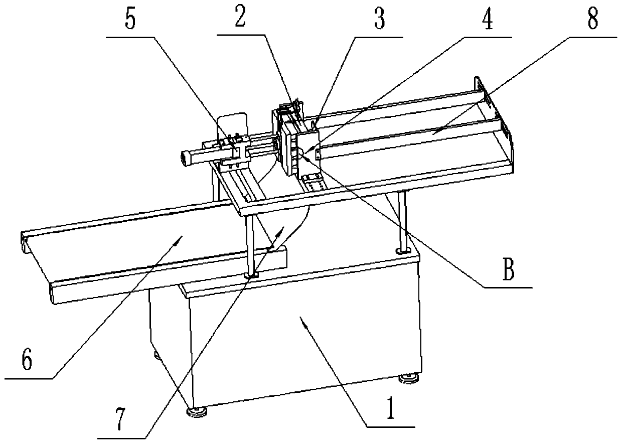
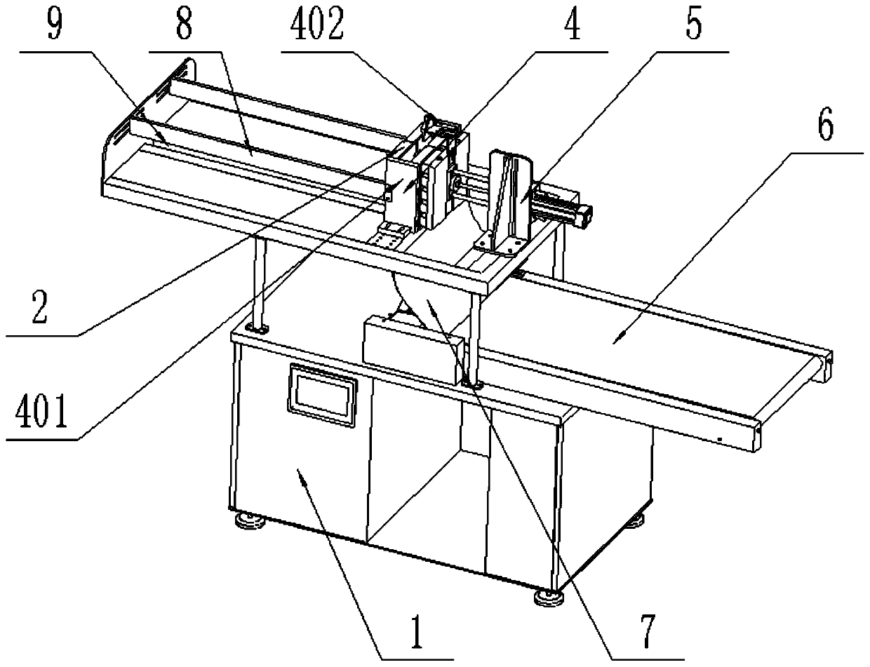
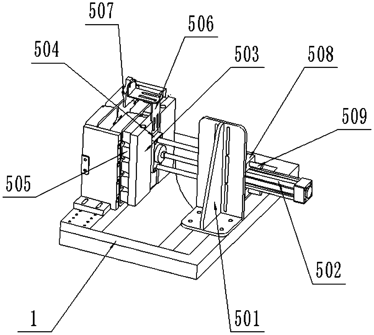
[0041] Such as Figure 1-12 As shown, a sorting machine includes a frame 1 on which a dodging mechanism 3, a tooth separation mechanism 4, a suction mechanism 5, and a box holder transmission device 6 are installed;

[0042] Dodging mechanism 3 comprises the upper supporting platform that is installed on the frame, and upper supporting platform 318 is provided with chute 9 along the direction of dodging, and push bracket 303 is installed movably in chute 9, and pushes bracket 303 tops and extends out chute installation. There is dodging plate 304, and dodging plate 304 is integrally formed into a flat plate to ensure the smoothness and strength of the pushing process; on the upper supporting platform 318, corresponding to the positions on both sides of the tooth separation mechanism 4, guard track plates 8 are installed along the dodging direction, during the dodging process Guide the box holder in the center. A guide rail 307 is installed on the bottom of the upper support p...


PUM


Abstract

The invention discloses a bracket separating machine and relates to the field of bracket separating equipment. The bracket separating machine comprises a rack. The rack is provided with a bracket pushing mechanism, a tooth separating mechanism, a bracket sucking mechanism and a box bracket conveying device. The bracket pushing mechanism comprises a bracket feeding platform arranged on the rack. Asliding groove is formed in the bracket feeding platform in the bracket pushing direction. A bracket pushing frame is movably arranged in the sliding groove. The upper portion of the bracket pushing frame extends out of the sliding groove to be provided with a bracket pushing plate. The bottom of the bracket feeding platform is provided with a guide rail in the bracket pushing direction. The rackis provided with a traction mechanism used for drawing the bracket pushing frame to move towards the tooth separating mechanism. The tooth separating mechanism is arranged at the tail end of the bracket feeding platform. The bracket sucking mechanism is arranged at a position, corresponding to the tooth separating mechanism, of the rack. The box bracket conveying device is arranged under the bracket sucking mechanism and is located on the rack. An arc-shaped bracket guiding plate is arranged between the bracket feeding platform and the box bracket conveying device on the rack. The lower end of the arc-shaped bracket guiding plate is connected with the box bracket conveying device. The bracket separating machine has the advantages of being good in bracket sucking effect and stable in bracket sucking and bracket pushing force, and requiring no external power source.

Description

technical field [0001] The invention relates to the technical field of plastic trays, in particular to a tray machine. Background technique [0002] In the field of packaging, a plastic tray is a carrying platform that can accommodate products, such as food trays, pharmaceutical plastic trays, pharmaceutical plastic trays include injection trays, oral liquid trays, or cillin trays, where injections, oral liquids, or vials are placed Insert it into the groove of the plastic holder, and then put it into the medicine box, so that it remains stable in the medicine box, so that two adjacent pieces will not collide with each other and be broken. The tray separating machine is a device specially used to separate the plastic trays. The tray separating machine sucks the plastic trays apart through the suction head that can generate negative pressure. A rotating mechanism is installed on the tray separating machine. The negative pressure of the head disappears, and the plastic tray f...

Claims


Application Information

Patent Timeline
Patent Type & Authority Applications(China)
IPC IPC(8): B65B43/42B65B43/46B65G47/08B65G47/91
CPCB65B43/42B65B43/46B65G47/084B65G47/912B65G2201/0267
Inventor 刘丙炎
Owner ZHENGZHOU SHUNYI TECH CO LTD
Why Eureka
Try Eureka