Rotary carrying robot

A technology for handling robots and clamping mechanisms, applied in the field of robots, can solve problems affecting product quality, position deviation and tilt, and corner damage of boxes, etc., to achieve the effects of preventing sliding deviation, ensuring integrity, and preventing damage

Inactive Publication Date: 2020-07-17
黄金榜
View PDF0 Cites 5 Cited by
  • Summary
  • Abstract
  • Description
  • Claims
  • Application Information

AI Technical Summary

Problems solved by technology

[0003] Since the surface of the box sealed with a packaging bag is smooth, when it is clamped and rotated, the box will generate an outward force due to the action of centrifugal force, and will slide to the side of the jaws, thereby causing the position of the box itself to change. The offset is inclined so that when the box is put down, the corners of the box will first touch the ground, and under the influence of gravity, the corners of the box will be damaged, which will affect the quality of the internal products

Method used


Image

  • Rotary carrying robot
  • Rotary carrying robot
  • Rotary carrying robot

Examples


Embodiment 1

[0030] Example 1: Please refer to Figure 1-Figure 8 , the specific embodiments of the present invention are as follows:

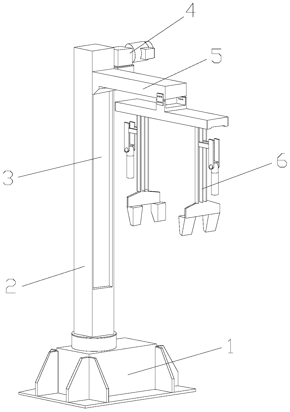
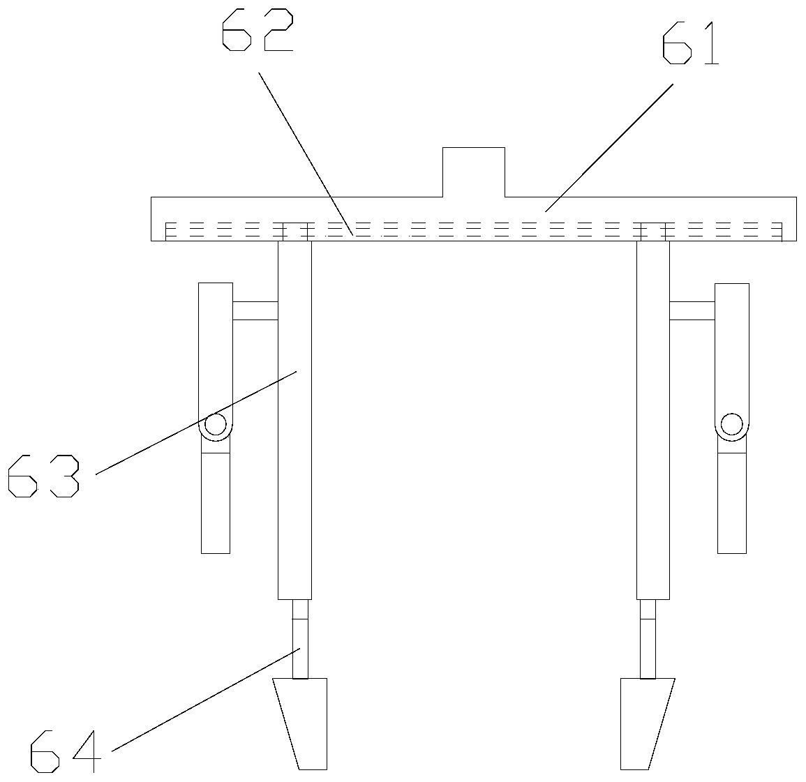
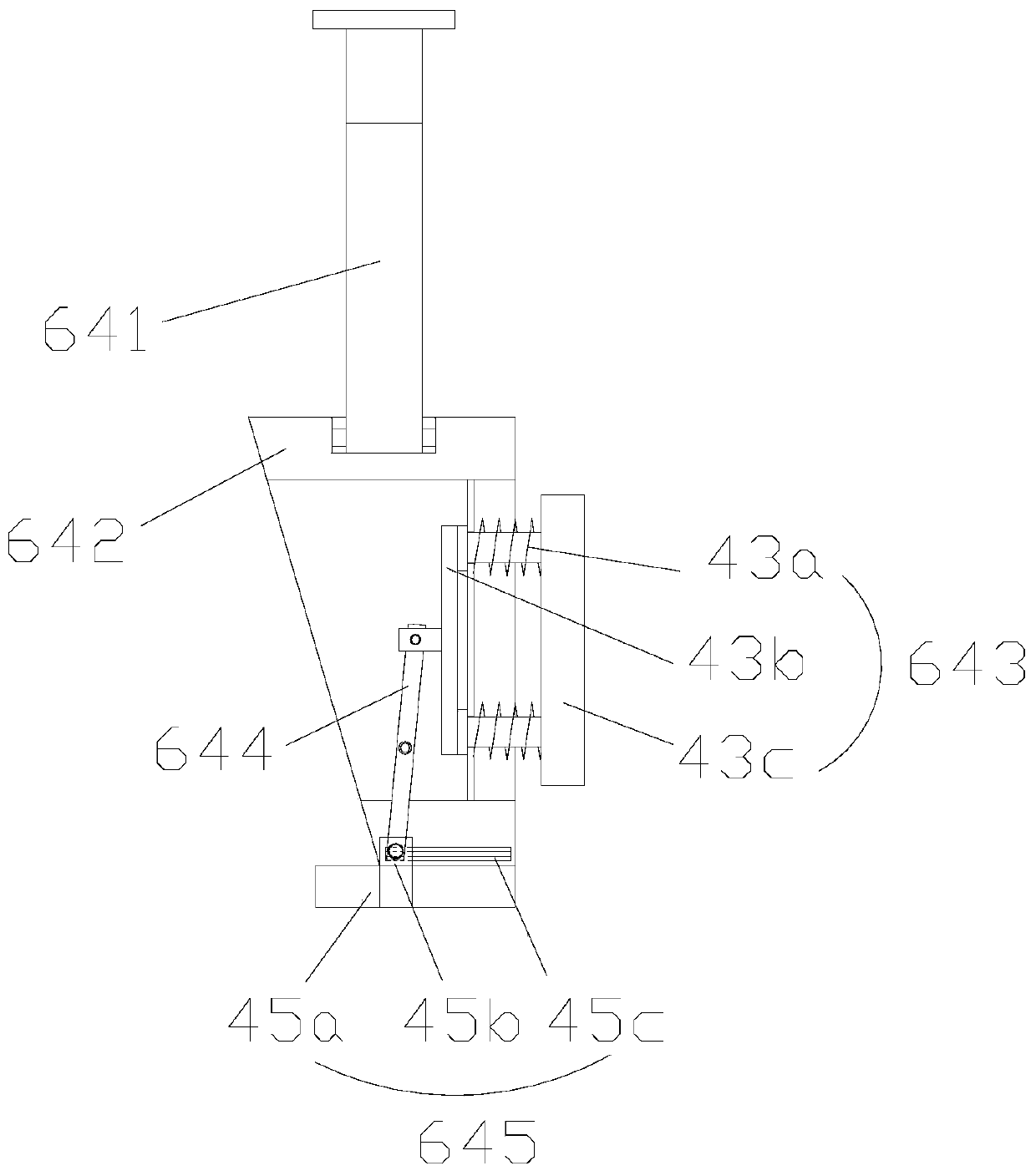
[0031] Its structure includes drive seat 1, support column 2, slideway 3, motor 4, horizontal frame 5, jaw 6, and described support column 2 is vertically installed on the upper end of drive seat 1 and adopts hinge connection, and described slideway 3 is set On the inner side of the support column 2 and is an integrated structure, the horizontal frame 5 is installed vertically on the inner side of the slideway 3 and adopts a flexible connection, the motor 4 is installed on the side of the horizontal frame 5 and adopts a mechanical connection, and the clamping jaws 6 are installed horizontally The lower end of the horizontal frame 5 and between them are fixed by bolts; the jaw 6 includes a fixed frame 61, a guide rail 62, a side clip body 63, and a clamping mechanism 64, and the guide rail 62 is arranged inside the fixed frame 61 and is an integrated struct...

Embodiment 2

[0038] Example 2: Please refer to Figure 1-Figure 2 , Figure 8-Figure 10 , the specific embodiments of the present invention are as follows:

[0039] Its structure includes drive seat 1, support column 2, slideway 3, motor 4, horizontal frame 5, jaw 6, and described support column 2 is vertically installed on the upper end of drive seat 1 and adopts hinge connection, and described slideway 3 is set On the inner side of the support column 2 and is an integrated structure, the horizontal frame 5 is installed vertically on the inner side of the slideway 3 and adopts a flexible connection, the motor 4 is installed on the side of the horizontal frame 5 and adopts a mechanical connection, and the clamping jaws 6 are installed horizontally The lower end of the horizontal frame 5 and between them are fixed by bolts; the jaw 6 includes a fixed frame 61, a guide rail 62, a side clip body 63, and a clamping mechanism 64, and the guide rail 62 is arranged inside the fixed frame 61 and ...


PUM


Abstract

The invention discloses a rotary carrying robot. The rotary carrying robot structurally comprises a driving seat, a supporting column, a sliding way, a motor, a transverse frame and a clamping jaw, wherein the supporting column is vertically installed at the upper end of the driving seat; the sliding way is arranged on the inner side of the supporting column; the transverse frame is vertically installed on the inner side of the sliding way; the motor is installed on the side face of the transverse frame; the clamping jaw is horizontally installed at the lower end of the transverse frame; and the clamping jaw comprises a fixing frame, a guide rail, a side clamping body and a clamping mechanism, the guide rail is arranged on the inner side of the fixing frame, the side clamping body is vertically installed at the lower end of the fixing frame, and the clamping mechanism is embedded into the inner side of the side clamping body. According to the rotary carrying robot, the clamping mechanism is arranged at the lower end of the side clamping body, due to limitation of the bottom and the side face, the clamping mechanism is kept balanced, and then damage to corners is prevented; and theside clamping body is arranged at the lower end of the fixing frame, the side face of a box is effectively limited, the upper end is also limited, thus sliding deviation caused by centrifugal force isprevented during rotation, and the integrity of the box corners and the quality of inner side products are ensured.

Description

technical field [0001] The invention belongs to the field of robots, and in particular relates to a rotary transfer robot. Background technique [0002] In the past, cargo handling was usually carried out by manpower and control equipment. With the continuous updating and progress of science and technology, handling robots have also been derived to carry out automatic handling and loading and unloading of goods. Among them, the rotary handling robot is mainly used in the original Carry out the handling and transfer of goods, and adjust the position, but the prior art has the following deficiencies: [0003] Since the surface of the box sealed with a packaging bag is smooth, when it is clamped and rotated, the box will generate an outward force due to the action of centrifugal force, and will slide to the side of the jaws, thereby causing the position of the box itself to change. The offset is inclined so that when the box is put down, the corners of the box will first touch...

Claims


Application Information

Patent Timeline
Patent Type & Authority Applications(China)
IPC IPC(8): B65G47/90
CPCB65G47/90
Inventor 黄金榜
Owner 黄金榜
Why Eureka
Try Eureka