Variable cross-section hollow thin-wall pier telescopic steel bar jig frame and jig frame set

A hollow, thin-walled, telescopic technology, which is applied in the erection/assembly of bridges, bridge parts, bridges, etc., can solve the difficulty of controlling the distance between steel bars and the control of steel bar cover, the difficulty of controlling the overall size of the steel bar skeleton, and the unsatisfactory construction process, etc. problems, to achieve the effect of improving the qualified rate of binding, effectively controlling the construction quality, and shortening the construction time

Pending Publication Date: 2020-07-17
ZHEJIANG ROAD & BRIDGE CONSTR
View PDF0 Cites 1 Cited by
  • Summary
  • Abstract
  • Description
  • Claims
  • Application Information

AI Technical Summary

Problems solved by technology

[0002] The variable cross-section hollow thin-walled pier reduces the structural size with the change of height, and the change ratio is 80:1. There are great difficulties in controlling the spacing of steel bars and the control of the protective layer of steel bars during construction.
[0003] During the construction of hollow thin-walled piers with variable cross-section, the auxiliary binding control of steel bars and the auxiliary control of electric welding of steel bars are generally used. The construction technology cannot meet the current construction requirements.
At the same time, it is very difficult to control the overall size of the steel skeleton during the construction process, and there is no effective construction method to control it

Method used


Image

  • Variable cross-section hollow thin-wall pier telescopic steel bar jig frame and jig frame set
  • Variable cross-section hollow thin-wall pier telescopic steel bar jig frame and jig frame set
  • Variable cross-section hollow thin-wall pier telescopic steel bar jig frame and jig frame set

Examples


Embodiment Construction

[0024] In order to illustrate the embodiments of the present invention more clearly, the specific implementation manners of the present invention will be described below with reference to the accompanying drawings. Obviously, the accompanying drawings in the following description are only some embodiments of the present invention, and those skilled in the art can obtain other accompanying drawings based on these drawings and obtain other implementations. In addition, the directional terms mentioned in the following embodiments, such as: up, down, left, right, front or back, etc., are only directions referring to the drawings. Accordingly, the directional terms are used to illustrate and not to limit the invention.

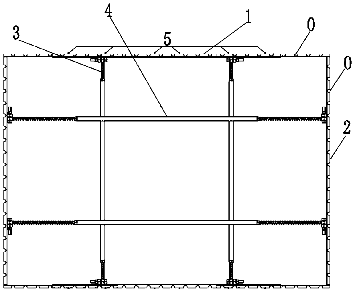
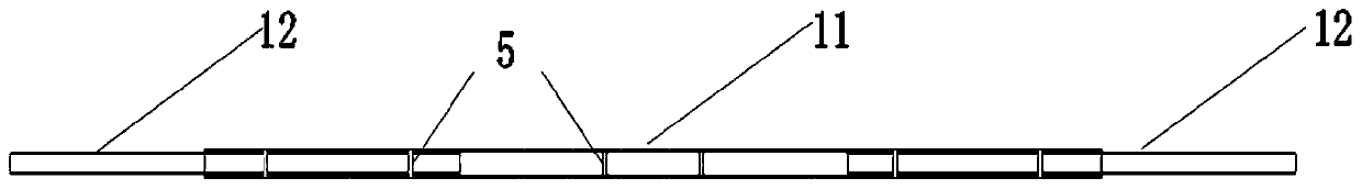
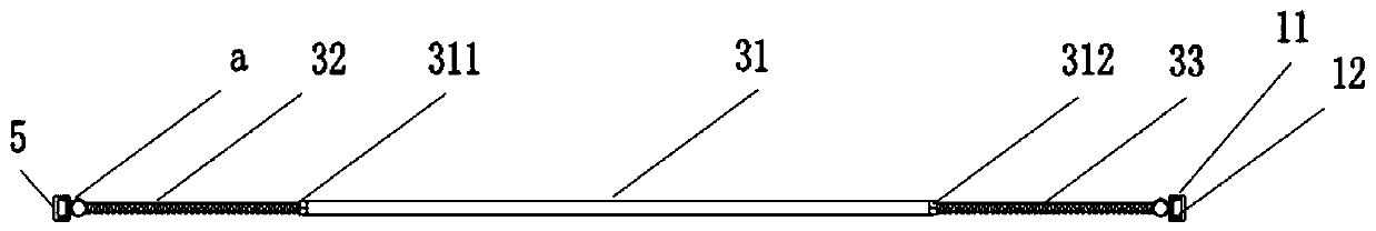
[0025] Such as Figure 1-5 As shown, the variable-section hollow thin-walled pier telescopic reinforced tire frame of the embodiment of the present invention includes two long-side formworks 1, two short-side formworks 2, two first distance-adjusting components 3...


PUM


Abstract

The invention relates to a variable cross-section hollow thin-wall pier telescopic steel bar jig frame. The jig frame comprises two long-edge mold frames, two short-edge mold frames, a first distanceadjusting assembly and a second distance adjusting assembly, wherein the two long-edge mold frames are oppositely arranged, the first distance adjusting assembly is arranged between the two long-edgemold frames, and the two ends of the first distance adjusting assembly are detachably connected with first steel channels of the corresponding long-edge mold frames respectively and used for adjustingthe distance between the two long-edge mold frames; the two short-edge mold frames are oppositely arranged, the second distance adjusting assembly is arranged between the two short-edge mold frames,and the two ends of the second distance adjusting assembly are detachably connected with the corresponding short-edge mold frames respectively and used for adjusting the distance between the two short-edge mold frames; the first distance adjusting assembly and the second distance adjusting assembly abut against each other so that the two long-edge mold frames and the two short-edge mold frames canform an annular structure. The long-side mold frames and the short-side mold frames are respectively provided with comb-shaped grooves distributed in the length directions of the long-side mold frames and the short-side mold frames, and the comb-shaped grooves are used for containing reinforcing steel bars. When the jig frame is used for binding steel bars, the overall binding size of a steel barframework is controlled to reach millimeter precision.

Description

technical field [0001] The invention belongs to the technical field of steel bar binding construction quality control, and in particular relates to a variable-section hollow thin-walled pier telescopic steel bar frame and a frame group. Background technique [0002] The hollow thin-walled pier with variable cross-section reduces the structural size with the change of height, and the change ratio is 80:1. It is very difficult to control the spacing of steel bars and the control of the protective layer of steel bars during construction. [0003] During the construction of the hollow thin-walled pier with variable cross-section, the auxiliary binding control of steel bars and the auxiliary control of electric welding of steel bars are generally used. The construction technology cannot meet the current construction requirements. The construction time is long, the overall effect is poor, and it consumes more labor. At the same time, it is very difficult to control the overall siz...

Claims


Application Information

Patent Timeline
Patent Type & Authority Applications(China)
IPC IPC(8): E01D21/00E01D19/02
CPCE01D19/02E01D21/00
Inventor 王玉富毛剑陈林隆斯纪平项向阳沈佳锋邓杭锋陈海虎张虎蒋维石川
Owner ZHEJIANG ROAD & BRIDGE CONSTR
Why Eureka
Try Eureka