Centrifugal water diversion device and implementation method thereof

A realization method, centrifugal technology, applied in the direction of non-variable pumps, pump control, driving pumps, etc., can solve the problems of abnormal drainage, water leakage, shortened service life of centrifugal pumps, etc., to avoid flameout shutdown and irrigation operations, The effect of ensuring the service life and reducing the working intensity

Pending Publication Date: 2020-07-17
蔡永波
View PDF0 Cites 0 Cited by
  • Summary
  • Abstract
  • Description
  • Claims
  • Application Information

AI Technical Summary

Problems solved by technology

[0004] 1. During the operation of the centrifugal pump, once the groundwater is less and the pump casing is not full of water, the centrifugal pump will be evacuated due to the air in the pump casing and the suction pipe, and the low pressure formed in the central area of ​​the impeller will not be able to The groundwater is pumped up, resulting in the problem of air binding and normal drainage. At this time, the centrifugal pump must be turned off and shut down, and then the pump casing and the suction pipe must be manually filled with water to empty the air in the pump casing and the suction pipe and then start the centrifugal pump. pump to continue draining
[0005] Moreover, because the centrifugal pump pumps open water, there are impurities in the water. When the centrifugal pump is turned off and shut down, the impurities may jam the bottom valve and prevent it from being completely closed, resulting in water leakage.
[0006] As a result, due to the need for repeated manual irrigation, and may also involve cleaning up the impurities stuck in the bottom valve (otherwise the water cannot be filled), the entire operation is very troublesome; It is easy to shorten the service life of the centrifugal pump
[0007] 2. The pumping pipe is directly connected to the pump casing. Before starting the centrifugal pump, it is necessary to manually fill the pump casing and the pumping pipe with water. The longer the pumping pipe is arranged, the greater the amount of water will be poured, and the higher the work intensity of the workers will be. Centrifugal pumps are more prone to air binding during operation
[0008] 3. During pumping and drainage operations, once the centrifugal pump is turned off and the bottom valve is not stuck by impurities, the bottom valve blocks the water in the pumping pipe from flowing back to the ground, and all of it is concentrated at the bottom of the pumping pipe, resulting in pumping The bottom end of the pipe is subjected to a very large water pressure in an instant, and it is easy to break the end of the pumping pipe. Therefore, it is necessary to provide auxiliary reinforcement and support to the bottom of the pumping pipe to avoid this problem, but this also further increases the complexity of the operation.

Method used


Image

  • Centrifugal water diversion device and implementation method thereof
  • Centrifugal water diversion device and implementation method thereof
  • Centrifugal water diversion device and implementation method thereof

Examples


Embodiment

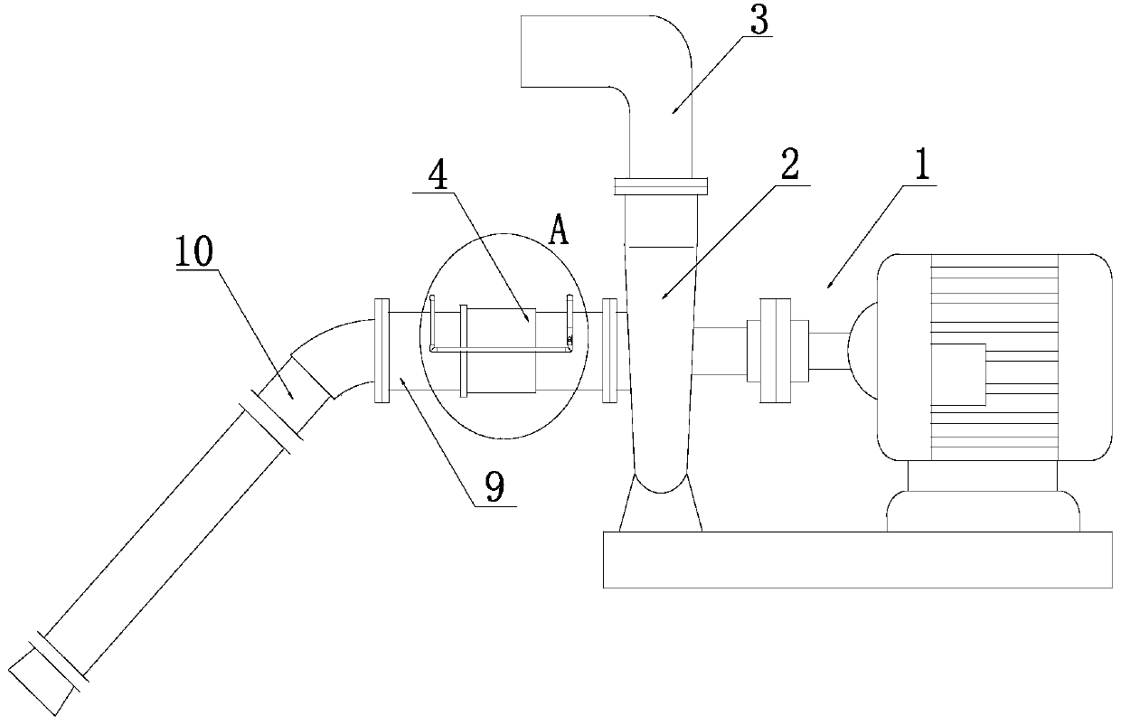
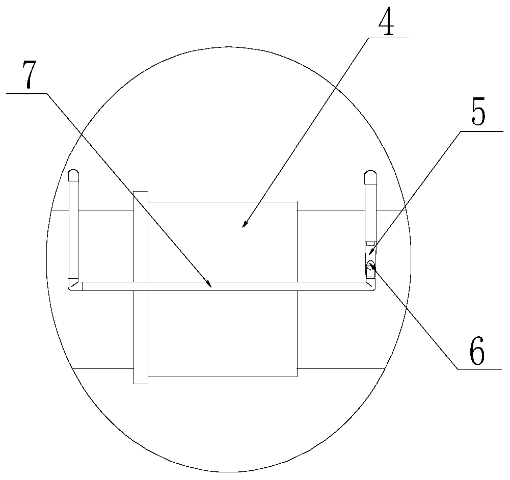
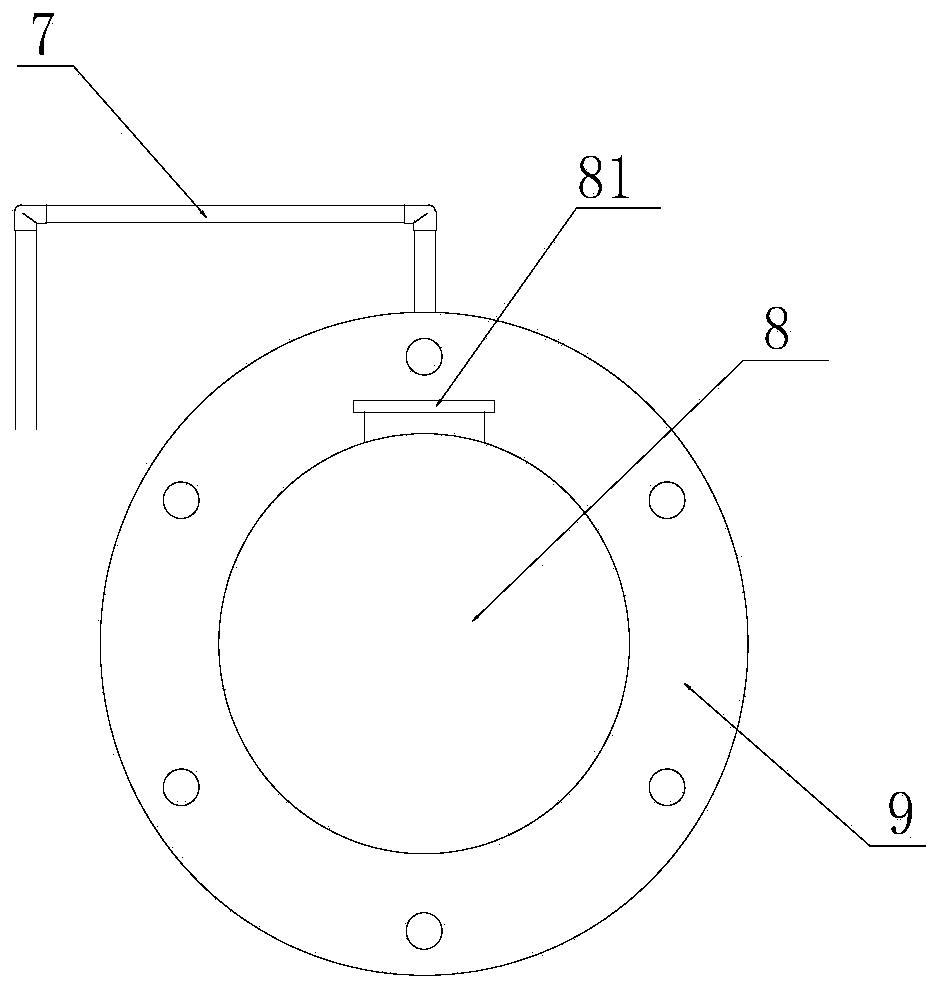
[0047] The invention provides a water diversion device, which is used in conjunction with a centrifugal pump to realize groundwater pumping and drainage. Such as Figure 1~4 As shown, the present invention mainly includes centrifugal pump 1, water injection pumping mechanism and water pumping pipeline 10 three major parts structurally, wherein, described water injection pumping mechanism is the core part of the whole scheme, and it comprises one end through a 45 ° elbow The first flange pipe 9 connected to the suction pipe 10, the second flange pipe 4 connected to the first flange pipe 9 at one end and the pump casing 2 of the centrifugal pump 1 (the pump casing is connected with the outlet pipe 3) at the other end , the check valve 8 that is arranged near the junction of the first flange pipe 9 and the second flange pipe 4 and can be reversed (the check valve 8 is connected with the end of the first flange pipe 9 through a rotating shaft 81, such as image 3 shown), and one ...


PUM


Abstract

The invention discloses a centrifugal water diversion device. The centrifugal water diversion device comprises a centrifugal pump of which a pump shell is connected with a discharging tube, a water injection and air exhaust mechanism and a water drawing pipeline of which one end stretches underground; the water injection and air exhaust mechanism comprises a first flange pipe of which one end is connected with the other end of the water drawing pipeline, a second flange pipe of which one end is connected with the first flange pipe while the other end is communicated with a pump shell of the centrifugal pump, a stop valve arranged at a connection part between the first flange pipe and the second flange pipe, and an exhaust pipe of which one end is communicated with the first flange pipe while the other end is communicated with the second flange pipe through an air exhaust mechanism. Based on a structure above, the invention also provides an implementation method of the centrifugal waterdiversion device. The device and the method provided by the invention are rational in design and convenient to use, not only avoid that stopping again and again and manual irrigation are needed in arunning process of the centrifugal pump, but also avoid a problem that an end part of the water drawing pipeline is liable to be broken by pressing, and well solve a difficult problem of the existingcentrifugal pump in practical application. Thus, the centrifugal water diversion device and the implementation method thereof are suitable for being generalized and used.

Description

technical field [0001] The invention relates to the technical field of water diversion, in particular to a centrifugal water diversion device and its realization method. Background technique [0002] Centrifugal pumps are the most common type of pump for moving fluids from one place to another and are used in a wide variety of applications today. Generally speaking, before the centrifugal pump is started, it is necessary to manually fill the pump casing and the suction pipe (hose) with water, and then start the centrifugal pump. After the centrifugal pump is started, the impeller rotates at a high speed driven by the motor to generate centrifugal force. At this time, the pressure near the impeller shaft decreases to form a partial vacuum. The atmospheric pressure forces the groundwater in the lower place to push the bottom valve at the end of the suction pipe, and then enters the pump along the suction pipe. The water in the pump casing and the pumped water are thrown into ...

Claims


Application Information

Patent Timeline
IPC IPC(8): F04D9/00F04D15/00
CPCF04D9/006F04D15/0022
Inventor 蔡永波
Owner 蔡永波
Why Eureka
Try Eureka