Supercharge Your Innovation With Domain-Expert AI Agents!

Winding distribution coefficient calculation model and method considering motor slot conductor distribution difference

A technology of distribution difference and winding distribution, applied in the field of electromechanics, can solve the problems of unsatisfactory motor control effect, deviation of physical model, unfavorable formation of basic theory and technical system of high-quality servo motor system, etc.

Pending Publication Date: 2020-07-17
SHENYANG POLYTECHNIC UNIV
View PDF2 Cites 2 Cited by
  • Summary
  • Abstract
  • Description
  • Claims
  • Application Information

AI Technical Summary

Problems solved by technology

[0005] The distribution coefficient is related to the mechanical angle of the slot distance or the electrical angle of the slot distance. However, the existing motor winding calculation models and methods usually only consider the distribution differences of the phase windings, coil groups, and turns in different motor slots, and ignore the motor slots. The difference in the distribution of the inner conductor in the spatial position, that is, a certain degree of "equivalent" and "simplification" is used to facilitate the modeling and analysis of the motor winding, but the introduction of this "equivalent" and "simplification" makes the motor winding model There is a certain degree of deviation from the actual physical model, which makes the motor control effect unsatisfactory, which is not conducive to the formation of the basic theory and technical system of high-quality servo motor system

Method used


Image

  • Winding distribution coefficient calculation model and method considering motor slot conductor distribution difference
  • Winding distribution coefficient calculation model and method considering motor slot conductor distribution difference
  • Winding distribution coefficient calculation model and method considering motor slot conductor distribution difference

Examples


Embodiment Construction

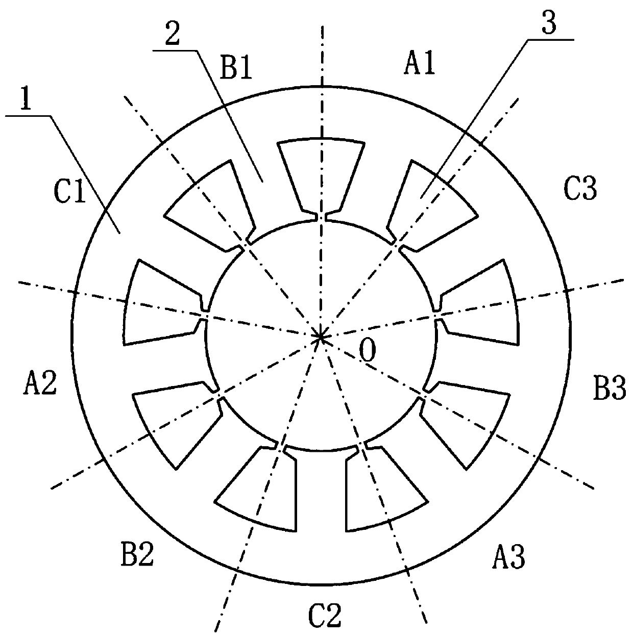
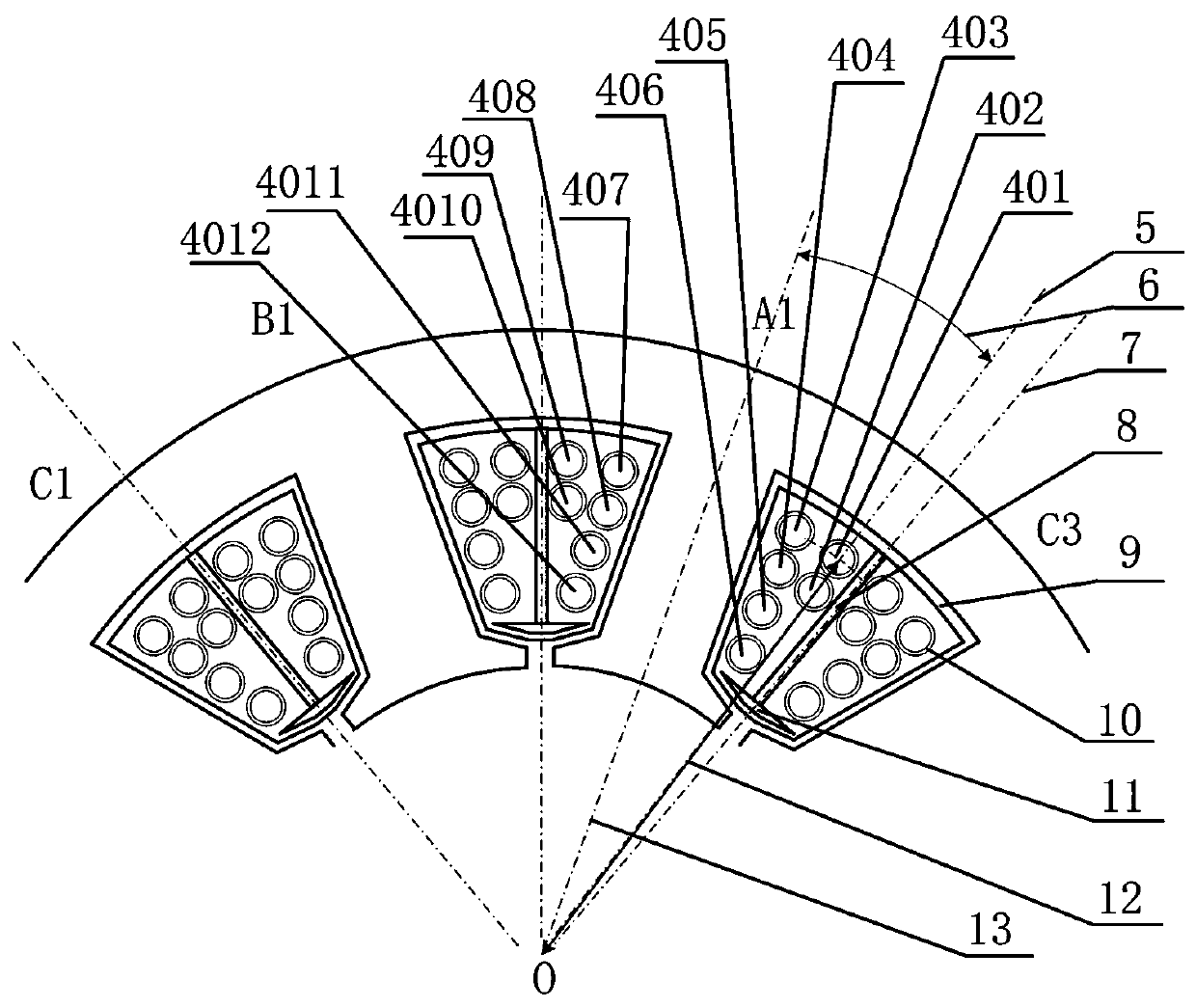
[0025] need for attached figure 2 And attached image 3 It is explained that A1, A2, and A3 belong to phase A of the motor, B1, B2, and B3 belong to phase B of the motor, C1, C2, and C3 belong to phase C of the motor, and O is the center point of the stamping of the motor stator.

[0026] The marked dotted lines are for the convenience of distinguishing the positions of different phases, and at the same time, A1, A2, A3, B1, B2, B3, C1, C2, C3, A, B, and C are only symbols representing different phases; 401—4012 The fact that there are 12 wires in the stator slot in this embodiment is only for the convenience of explaining this embodiment, and does not limit the number of wires in the stator slot in this embodiment.

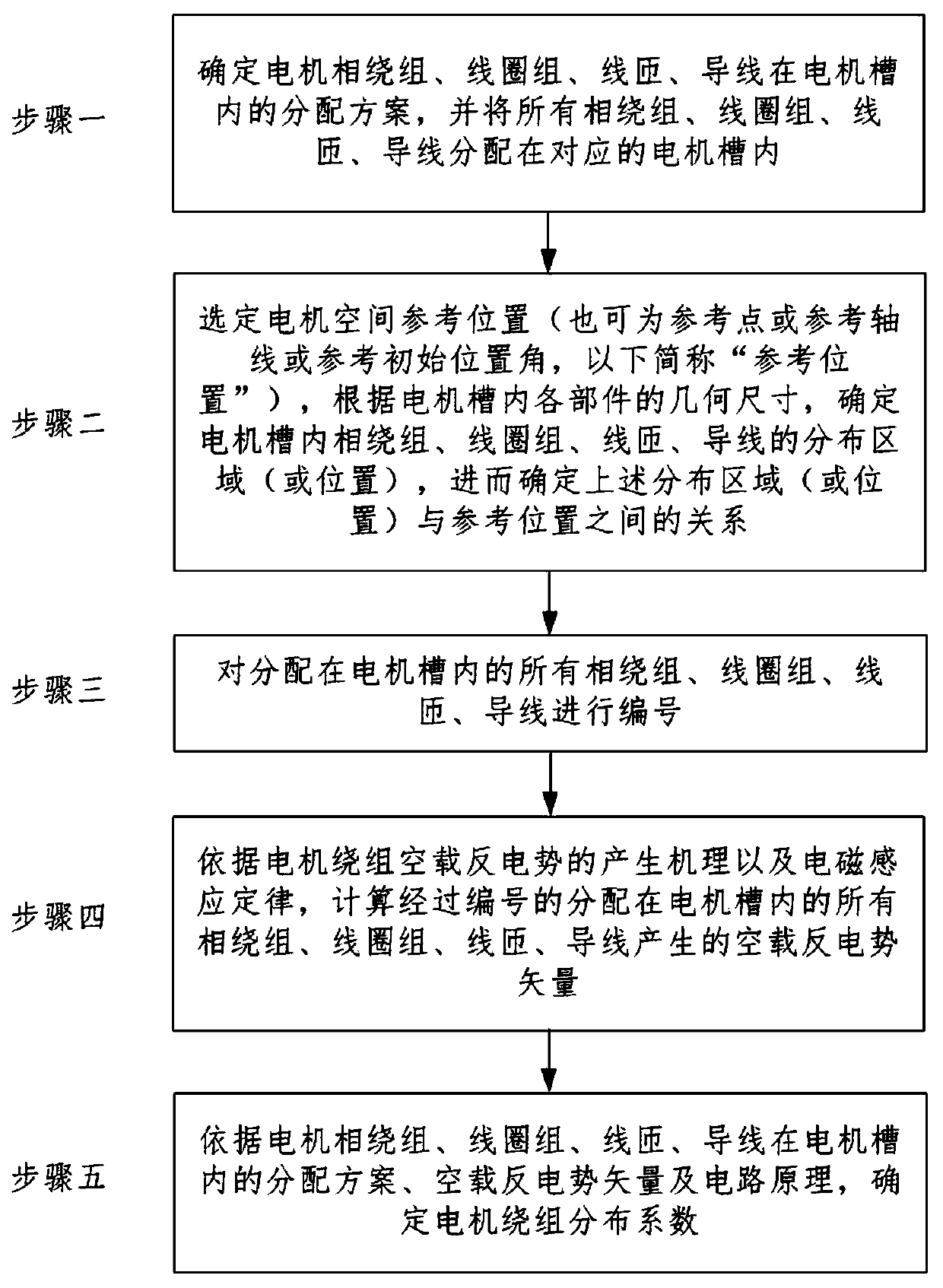
[0027] Such as figure 1 Shown is the implementation steps of the present invention.

[0028] A winding distribution coefficient calculation model and method that considers the difference in the distribution of conductors in the motor slot, which fully conside...


PUM


Abstract

The invention belongs to the field of motor science, and particularly relates to a winding distribution coefficient calculation model and method considering motor slot conductor distribution difference. Modeling and analysis of the motor winding are more accurate. The method comprises the steps of 1, determining a distribution scheme of motor phase windings, coil assemblies, wire turns and wires in motor grooves according to a motor design scheme, and distributing all the phase windings, the coil assemblies, the wire turns and the wires in the corresponding motor grooves; 2, selecting a motorspace reference position, and determining a distribution area of a phase winding, a coil assembly, a wire turn and a wire in the motor groove according to the geometric dimension of each part in the motor groove; and 3, numbering all the phase windings, the coil assemblies, the wire turns and the wires distributed in the motor grooves; step 4, calculating no-load back electromotive force vectors generated by all the phase windings, coil assemblies, wire turns and wires which are numbered and distributed in the motor groove; and step 5, determining a motor winding distribution coefficient, andfurther performing subsequent research by utilizing the coefficient.

Description

technical field [0001] The invention relates to a calculation model and method of distribution coefficients of motor windings, in particular to a calculation model and method of distribution coefficients of windings considering differences in conductor distribution in motor slots, and belongs to the field of electromechanics. Background technique [0002] With the continuous development of motor design theory, analysis theory and control theory, special motors of different types, structures and functions have gradually appeared, and have been widely used in many fields and industries. [0003] Usually, in the theoretical research and engineering control of electric motors, it is a common step to establish a mathematical model of the electric motor and determine the control algorithm based on the physical model of the electric motor, winding theory, and operating mechanism. In recent years, with the emergence of motor servo control systems and precision control systems, as we...

Claims


Application Information

Patent Timeline
Patent Type & Authority Applications(China)
IPC IPC(8): G06F30/20G06F30/10G06F111/10
Inventor 张志恒安跃军邓文宇王光玉齐丽君孔祥玲毕德龙李明李嘉欣
Owner SHENYANG POLYTECHNIC UNIV
Features
  • R&D
  • Intellectual Property
  • Life Sciences
  • Materials
  • Tech Scout
  • Unparalleled Data Quality
  • Higher Quality Content
  • 60% Fewer Hallucinations
Learn More