Cable laying traction device and method for intelligent pipe gallery construction
A cable laying and pulling device technology, used in cable installation devices, cable installation, cable laying equipment, etc., can solve the problem of limited number of clamped cables, inconvenience for pulling multiple cables of the same specification, and inconvenience for cables to move to the required Position and other issues, to achieve the effect of stable clamping and simple and convenient operation.
- Summary
- Abstract
- Description
- Claims
- Application Information
AI Technical Summary
Problems solved by technology
Method used
Image

Examples
Embodiment 1
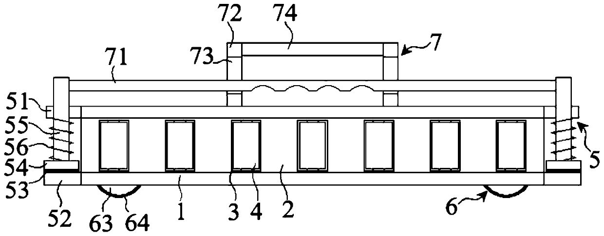
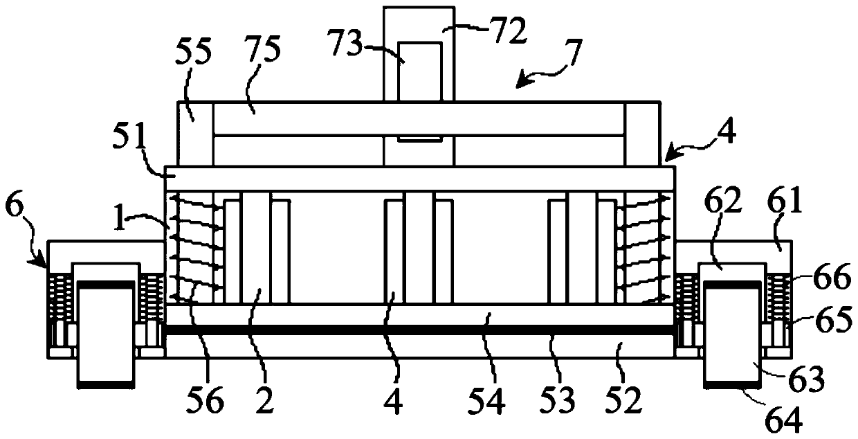
[0036] combine figure 1 with figure 2 , a cable laying traction device for smart pipe gallery construction in this embodiment, including a main warehouse body 1 , a clamping mechanism 5 , a moving mechanism 6 and a pulling mechanism 7 . The inside of the main bin body 1 is fixed with a plurality of mutually parallel baffles 2 along its width direction, and each baffle 2 is provided with a plurality of auxiliary holes 3 along its length direction, and auxiliary rollers 4 are arranged in the auxiliary holes 3 , rotate vertically along its axis; the cable penetrates the main bin body 1 from between the baffles 2, and moves smoothly in the main bin body 1 with the aid of auxiliary rollers 4.
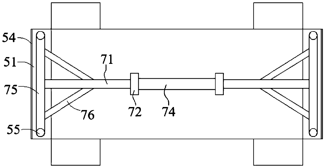
[0037] Described clamping mechanism 5 is provided with two, is respectively positioned at main chamber body 1 two sides, and this clamping mechanism 5 comprises upper plate 51, lower plate 52, splint 54, slide bar 55 and clamping spring 56, and upper plate 51 and the lower plate 52 are re...
Embodiment 2
[0043] A cable laying traction device for smart utility gallery construction in this embodiment is basically the same as that in Embodiment 1, except that the pulling mechanism 7 further includes a side plate 72 and a pull handle 74 .
[0044] combine figure 1 with figure 2 , the side plate 72 is provided with two, which are fixed at the top of the main compartment body 1 at a certain distance, and the tops of the two side plates 72 are connected by a pull handle 74, and a side sliding hole 73 is opened on the side plate 72. The pull rod 71 passes through the side sliding hole 73, and can move up and down in the side sliding hole 73.
[0045] On the one hand, the operator can drive the whole device to move to the desired position through the pull handle 74 to complete the traction work. On the one hand, the pull handle 74 can be used to control the pull rod 71 to complete the clamping work more conveniently. The whole operation is simple and labor-saving.
Embodiment 3
[0047] A cable laying traction method for smart pipe gallery construction in this embodiment uses the traction device described in Embodiment 2, and the steps are as follows:
[0048] Step 1. Pull up the connecting rod 75 to separate the splint 54 from the lower plate 52, put the cable between two adjacent baffles 2, and make the cable pass through the entire main compartment body 1;
[0049] Step 2, put down the connecting rod 75, the splint 54 approaches the lower plate 52 under the action of the clamping spring 56, and clamp and fix the cable; manually hold the pull handle 74, and drive the whole device to move to the desired position;
[0050] Step 3, after arriving at the destination, pull the connecting rod 75 upwards, and continue to push the whole device to move, so that the cable is separated from the device.
[0051] When the cable passes through the entire main compartment body 1, the cable can be clamped by the splints 54 located on both sides of the main compartme...
PUM
 Abstract
Description
Claims
Application Information
 - R&D
- Intellectual Property
- Life Sciences
- Materials
- Tech Scout
- Unparalleled Data Quality
- Higher Quality Content
- 60% Fewer Hallucinations
Browse by: Latest US Patents, China's latest patents, Technical Efficacy Thesaurus, Application Domain, Technology Topic, Popular Technical Reports.
© 2025 PatSnap. All rights reserved.Legal|Privacy policy|Modern Slavery Act Transparency Statement|Sitemap|About US| Contact US: help@patsnap.com