Manpower-driven single-cutter cutting type wire stripping device

A human-driven, cutting-type technology, used in cable installation devices, cable installation, circuits, etc., can solve the problem of laborious wire insulation sleeves, and achieve good protection effects.

Active Publication Date: 2020-07-17
ANHUI XINDALU SPECIAL PAINT CO LTD
View PDF10 Cites 2 Cited by
  • Summary
  • Abstract
  • Description
  • Claims
  • Application Information

AI Technical Summary

Problems solved by technology

[0003] The invention provides a human-driven single-knife cutting type wire stripping device with good protection effect on the blade, which solves the laborious problem of manually cutting the wire insulation sleeve with a knife

Method used


Image

  • Manpower-driven single-cutter cutting type wire stripping device
  • Manpower-driven single-cutter cutting type wire stripping device

Examples


Embodiment 1

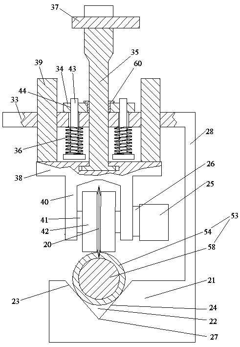
[0021] Embodiment one, see figure 1 , a human-driven single-knife cutting type wire stripping device, including a support table 21 and a cutting knife assembly. A "V"-shaped centering straight groove 22 extending along the front-to-back direction is provided on the support table. The inclination angle of the left side wall 23 of the centering groove is equal to the inclination angle of the right side wall 24 of the centering groove. The cutting knife assembly comprises a circular cutting blade 20, a fixed plate 33, a movable plate 34, a blade mounting bar 35 and a blade pressing spring 36 that drives the movable plate to abut against the fixed plate. The fixed plate is connected on the support platform through the stand 28. The movable plate is provided with a through hole, and an internal thread sleeve 60 is fixed in the through hole. The inner space of the internal thread sleeve constitutes the threaded hole on the movable plate. One end of the blade mounting rod is thre...

Embodiment 2

[0023] Embodiment two, the difference with embodiment one is:

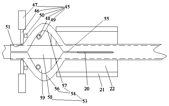
[0024] see figure 2It also includes a pair of sleeve core separation mechanisms 45 distributed along the axial direction of the feed wheel to separate the part of the wire insulation sleeve cut by the circular cutting blade from the wire conductive core. The sleeve core separation mechanism includes a push rod 46, a push rod driving cylinder 47 for driving the push rod to be pressed onto the wire insulation sleeve, and a cylinder extending in the up and down direction for blocking between the conductive core of the wire and the wire insulation sleeve in a separated state. Separation rod 48, driving separation rod lifting cylinder 49 of separation rod lifting and withstood the wire insulation sleeve when the push rod leaves the wire insulation sleeve and makes the cross push rod 50 separate from the wire insulation sleeve. A nail head 51 is provided at one end of the wire insulating sleeve on the top of the top p...


PUM


Abstract

The invention relates to a manpower-driven single-cutter cutting type wire stripping device. The device comprises a sectioning knife assembly and a supporting table board provided with a V-shaped centering straight groove., t The inclination angles of the two side walls of the centering groove are equal; the sectioning knife assembly comprises a circular cutting blade, a fixed plate, a movable plate, a blade mounting rod and a blade pressing spring for driving the movable plate to be propped against the fixed plate; one end of the blade mounting rod is connected with the movable plate; the circular cutting blade is connected to the other end of the blade mounting installation rod, the movable plate and the circular cutting blade are distributed on the two sides of the fixed plate, the fixed plate is connected to the supporting table top through a vertical frame, the circular cutting blade is located above the centering straight groove, and the intersecting line of the two planes wherethe two side walls of the centering straight groove are located is located on the plane where the circular cutting blade is locatted. The invention provides aAccording to the manpower-driven single-cutter cutting type wire stripping device which has a good protection effect on a blade, and solves the problem that the manual cutting of a the wire insulation sleeve by using a cutter is strenuouslabor-consuming can be solved.

Description

technical field [0001] The invention relates to the technical field of electric appliance construction and waste product recycling, in particular to a human-driven single-knife cutting electric wire stripping device. Background technique [0002] The electric wire is composed of a wire conductive core of a metal structure and a wire insulating sleeve of an insulating structure wrapped outside the conductive core of the wire. In the process of electric power construction or waste recycling, it is necessary to peel off the wire insulation sleeve of the wire (some of them peel off a section of a wire, and some of the wire insulation sleeve on the entire wire is peeled off). Since the wire stripper is only suitable for stripping the short length of the power supply, the existing longer length or the overall stripping of the wire insulation sleeve is manually cut with a knife to open the wire insulation sleeve and then torn off, and the knife is cut manually. The wire insulation...

Claims


Application Information

Patent Timeline
Patent Type & Authority Applications(China)
IPC IPC(8): H02G1/12H01B15/00
CPCH01B15/006H02G1/1217Y02W30/82
Inventor 郑伟哲
Owner ANHUI XINDALU SPECIAL PAINT CO LTD
Why Eureka
Try Eureka