A communication cable support device

A supporting device and cable technology, applied in electromechanical devices, spatial arrangement/configuration of cables, mechanical vibration attenuation devices, etc., can solve the problems of cables being entangled, endangering the health of surrounding residents, affecting signal transmission, etc., to prevent bundling Effect

Inactive Publication Date: 2021-04-06
徐雄敏
View PDF11 Cites 0 Cited by
  • Summary
  • Abstract
  • Description
  • Claims
  • Application Information

AI Technical Summary

Problems solved by technology

[0002] Cable is an essential transmission medium in communication engineering. In cities, it is often seen that many cables are bundled together and placed in the air. Once encountering strong winds, the cables will swing greatly with the wind, which is prone to accidents. , and a large number of cables are entangled, which affects the transmission of signals, and at the same time generates electrical radiation that endangers the health of surrounding residents, and repairing the cables in the air requires professional maintenance personnel to work at heights, which also poses safety hazards

Method used


Image

  • A communication cable support device
  • A communication cable support device
  • A communication cable support device

Examples


specific Embodiment approach 1

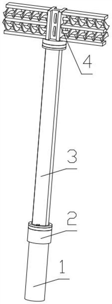
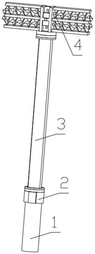
[0034] Combine below Figure 1-14 Description of this embodiment, a cable support device for communication, including a buried pile 1, the pedal mechanism 2 is fixedly connected to the buried pile 1, the sealing mechanism 3 is installed on the pedal mechanism 2, and the cable fixing mechanism 4 is fixed Installed on the pedal mechanism 2.

specific Embodiment approach 2

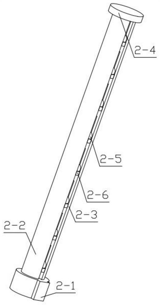
[0036] Combine below Figure 1-14Describe this embodiment, this embodiment will further explain the first embodiment, the pedal mechanism 2 includes a bottom installation shell 2-1, a half cylinder 2-2, a half cylinder 2 2-3, and a top circular plate 2-4 , Climbing stick with gear 2-5, block 2-6, threaded post 2-7, double-sided tooth pattern block 2-8, driven helical gear 2-9, driving helical gear 2-10, main motor 2-11 , connect the stub 2-12, the main motor 2-11 is fixedly installed on the groove provided on the bottom installation shell 2-1, the active helical gear 2-10 is fixedly installed on the output end of the main motor 2-11, the active helical gear 2-10 meshes with the driven helical gear 2-9, the driven helical gear 2-9 is rotatably installed on the groove provided on the bottom mounting shell 2-1, and the driving helical gear 2-10 is rotatably mounted on the bottom mounting shell 2 On the groove provided on -1, the driven helical gear 2-9 is fixedly connected with ...

specific Embodiment approach 3

[0038] Combine below Figure 1-14 Describe this embodiment, this embodiment will further explain the second embodiment, the sealing mechanism 3 includes a bottom ball bearing 3-1, a bearing sealing ring plate 3-2, an arc plate 3-3, and an arc plate two 3-4. The top sealing ring plate 3-5, the top ball bearing 3-6, the movable clip 3-7, the outer ring of the bottom ball bearing 3-1 is fixedly installed on the bottom installation shell 2-1, and the bearing sealing ring plate 3-2 is fixedly installed on the outer ring of the bottom ball bearing 3-1, one end of the arc-shaped plate 3-3 is fixedly installed on the inner ring of the bottom ball bearing 3-1, and one end of the arc-shaped plate 2 3-4 is fixed Installed on the inner ring of the bottom ball bearing 3-1, the movable clip 3-7 is hinged with the arc plate 2 3-4, and the movable clip 3-7 is movably installed on the U of the bearing sealing ring plate 3-2. The other end of the curved plate 3-3 is fixedly installed on the in...


PUM


Abstract

The present invention relates to a communication-related device, more specifically a cable support device for communication, including a buried pile, the pedal mechanism is fixedly connected to the buried pile, the sealing mechanism is installed on the pedal mechanism, and the cable The fixing mechanism is fixedly installed on the foot pedal mechanism. This device has an auxiliary climbing function, which is convenient for maintenance personnel to work on heights and reduces the occurrence of danger. When it is windy, it has a certain buffering effect.

Description

technical field [0001] The invention relates to a communication-related device, more specifically a communication cable support device. Background technique [0002] Cable is an essential transmission medium in communication engineering. In cities, it is often seen that many cables are bundled together and placed in the air. Once encountering strong winds, the cables will swing greatly with the wind, which is prone to accidents. , and a large number of cables are entangled, which affects the transmission of signals, and at the same time generates electrical radiation that endangers the health of surrounding residents, and repairing the cables in the air requires professional maintenance personnel to work at heights, which also poses safety hazards. Contents of the invention [0003] The main technical problem to be solved by the present invention is to provide a communication cable supporting device. This device has an auxiliary climbing function, which is convenient for m...

Claims


Application Information

Patent Timeline
Patent Type & Authority Patents(China)
IPC IPC(8): H02G7/20H02G7/14H02G1/02H02K7/06
CPCH02G1/02H02G7/14H02G7/20H02K7/06
Inventor 徐雄敏马玉龙
Owner 徐雄敏
Why Eureka
Try Eureka