Storage type router
A router and storage box technology, applied in the direction of selecting devices, electrical components, etc., can solve the problems of easy entanglement of network cables and power cables, low router disassembly and assembly efficiency, inconvenient router maintenance, etc., to improve disassembly efficiency and prolong service life. , The effect of reducing dust content
- Summary
- Abstract
- Description
- Claims
- Application Information
AI Technical Summary
Problems solved by technology
Method used
Image

Examples
Embodiment Construction
[0028] The technical solutions in the embodiments of the present invention will be clearly and completely described below in conjunction with the embodiments of the present invention. Apparently, the described embodiments are only some of the embodiments of the present invention, not all of them. Based on the embodiments of the present invention, all other embodiments obtained by persons of ordinary skill in the art without creative efforts fall within the protection scope of the present invention.
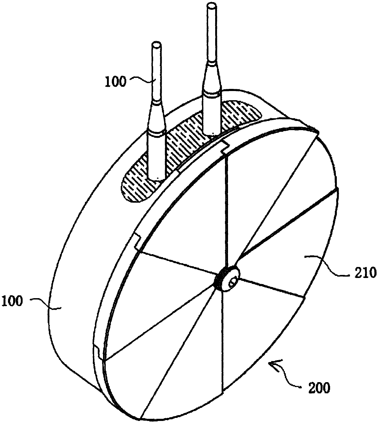
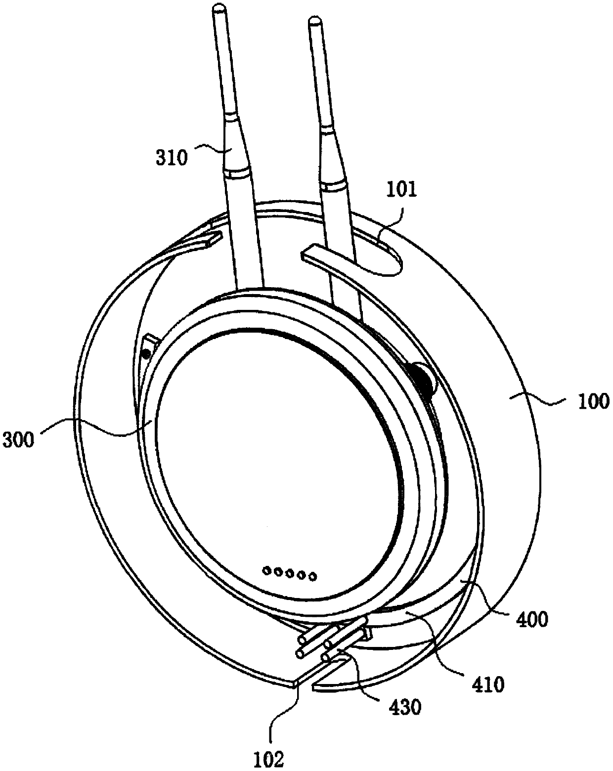
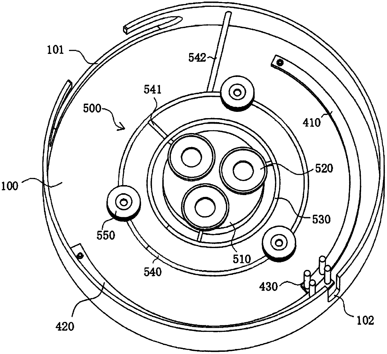
[0029] see Figure 1-9 As shown, a storage router includes a router body 300 and a storage box 100 arranged outside the router body 300; the storage box 100 is a cylindrical shell structure, and the top and bottom of the storage box 100 are respectively provided with a No. 1 through hole 101 and the No. 2 through hole 102, the outside of the open end of the storage box 100 is provided with a sliding card slot 103, the open end of the storage box 100 is provided with a closed modul...
PUM
 Abstract
Description
Claims
Application Information