Cutting blade and cutting device using same

A blade and cutting part technology, applied in the field of cutting devices, can solve the problem of difficulty in forming high-precision blade blades, and achieve the effect of improving cutting force

Active Publication Date: 2020-07-24
金模珍
View PDF10 Cites 0 Cited by
  • Summary
  • Abstract
  • Description
  • Claims
  • Application Information

AI Technical Summary

Problems solved by technology

However, when both the blade body and the blade are made of PCD, there is a problem that it is

Method used


Image

  • Cutting blade and cutting device using same
  • Cutting blade and cutting device using same
  • Cutting blade and cutting device using same

Examples


Embodiment Construction

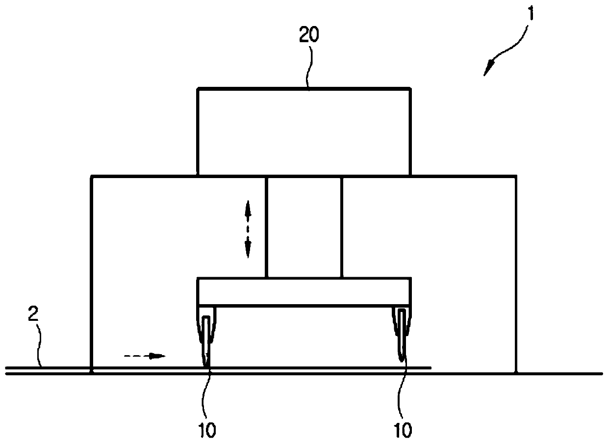
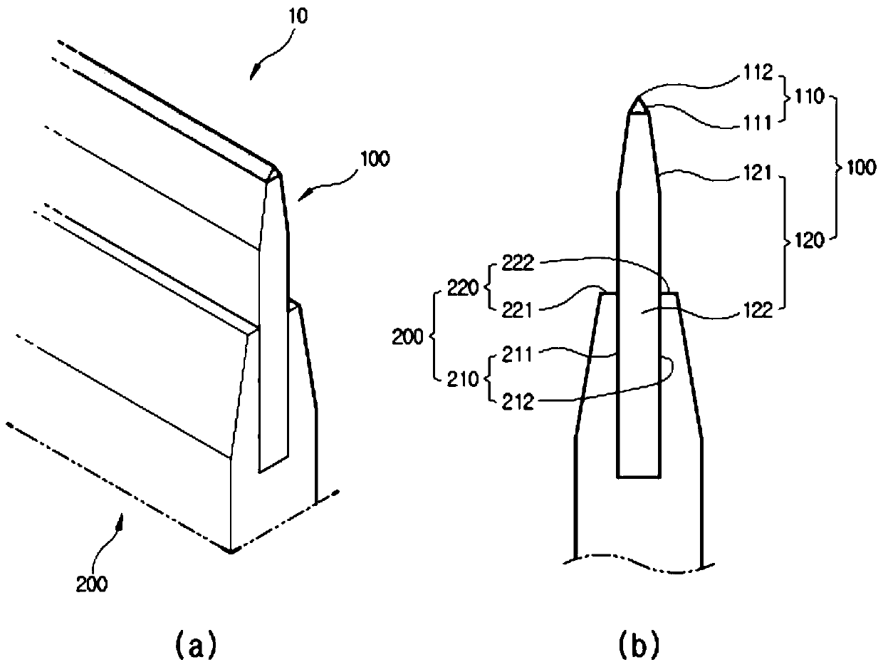
[0030] Hereinafter, the cutting device 1 and the blade 10 according to preferred embodiments of the present invention will be described in detail with reference to the drawings.

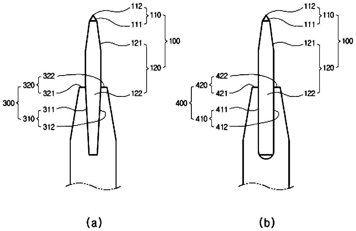
[0031] figure 1 is a schematic illustration of a cutting device 1 according to the present invention, figure 2 are detailed drawings (a), (b) of the blade 10, image 3 is a deformation example diagram of the blade 10, Figure 4 is a manufacturing process diagram of the blade 10.

[0032] The cutting device 1 includes a blade 10 and a blade driving unit 20 . The blade driving part 20 includes: a blade clamping part (not shown), which clamps the blade 10; an up and down moving shaft (not shown), which is connected with the blade clamping part; an up and down moving motor (not shown), which Rotating the vertical movement shaft causes the blade clamping portion to move up and down. In order to manufacture a semiconductor component 2 including an MLCC (Multilayer Ceramic Capacitor) 2 , the blade dri...


PUM


Abstract

A cutting blade for manufacturing semiconductor components including a multi-layer ceramic condenser (MLCC) includes: a blade unit having a cutting part made of a polycrystalline diamond (PCD) material manufactured at a predetermined temperature and a predetermined pressure, having a mutually opposite nose inclined surface, and forming a cutting nose in a longitudinal direction and a support extension part extended from the other side of the cutting part to support the cutting unit; and a blade support unit having a receiving coupling part dented to receive a part of the support extension partin a longitudinal direction and to be coupled thereto.

Description

technical field [0001] The present invention relates to a cutting blade and a cutting device using the same, and more specifically, to a cutting blade for manufacturing semiconductor components including MLCC (Multi Layer Ceramic Condenser) and a cutting device using the same. device. Background technique [0002] With the development of smartphones and electric vehicles, components such as multilayer ceramic capacitors and chip inductors are becoming more functional, lightweight and miniaturized. In particular, MLCCs (Multi-Layer Ceramic Condensers (or Capacitors)) in which capacitors are stacked in multiple layers not only increase the number of stacks but also reduce their size. After the MLCC is formed into a plate-like process that is widely stacked, the MLCC material is cut to a desired size by a cutting device with blades to form a finished product. As the number of stacks and miniaturization progress, in order to cut MLCC, the material of the blade is a cemented ca...

Claims


Application Information

Patent Timeline
IPC IPC(8): B28D1/22B28D7/00
CPCB28D1/22B28D7/00H01L21/67092B26D1/0006B26D7/2614B26D2001/002
Inventor 金模珍
Owner 金模珍
Why Eureka
Try Eureka