Flap and slat system

A slat and flap technology, which is applied in aircraft component testing, aircraft parts, aircraft control, etc., can solve the problems of overly conservative disposal methods, insufficient use of tilt sensors, and reduced performance and efficiency of flap and slat systems

Active Publication Date: 2020-07-24
COMAC +1
View PDF8 Cites 0 Cited by
  • Summary
  • Abstract
  • Description
  • Claims
  • Application Information

AI Technical Summary

Problems solved by technology

however, this approach is too conservative and clearly reduces the performance and efficiency of the flap and slat system, while also underutilizing the tilt sensor

Method used


Image

  • Flap and slat system
  • Flap and slat system
  • Flap and slat system

Examples


Embodiment approach 1

[0093] The aircraft of this embodiment (embodiment 1) does not possess the function of changing the camber of the wing. Each side flap has a position sensor. Here, assume that the position sensor of the left flap fails as an example.

[0094] In this embodiment (Embodiment 1), the electrical characteristics of the two channels of the position sensors on the left and right sides are basically similar, and the output voltage values ​​of the flap surfaces at aerodynamic zero are basically the same.

[0095] In addition, after the electronic adjustment of the flap control system is completed, the output voltage value of channel 1 of the left position sensor is PSU L1RiggingOutput1 , the output voltage value of channel 2 of the left position sensor is PSU L2RiggingOutput , while the output voltage value of channel 1 of the right position sensor is PSU R1RiggingOutput , the output voltage value of channel 2 of the right position sensor is PSU R2RiggingOutput . At this point, the...

Embodiment approach 2

[0116] The aircraft of this embodiment (embodiment 2) does not possess the function of changing the camber of the wing. Each side flap has a position sensor. Here, assume that the position sensor of the left flap fails as an example.

[0117] In the previous embodiment (Embodiment 1), the electrical characteristics of the two channels of the position sensors on the left and right sides are basically similar, and the output voltage value of the flap surface is basically the same at aerodynamic zero. Therefore, there is no need to establish and use The functional relationship f(x) between the output voltage value of the tilt sensor 170 and the airfoil angle. Similarly, at this time, the functional relationship f(x) between the output voltage value of the tilt sensor 170 and the airfoil angle needs to be established, and stored in the slat control computer.

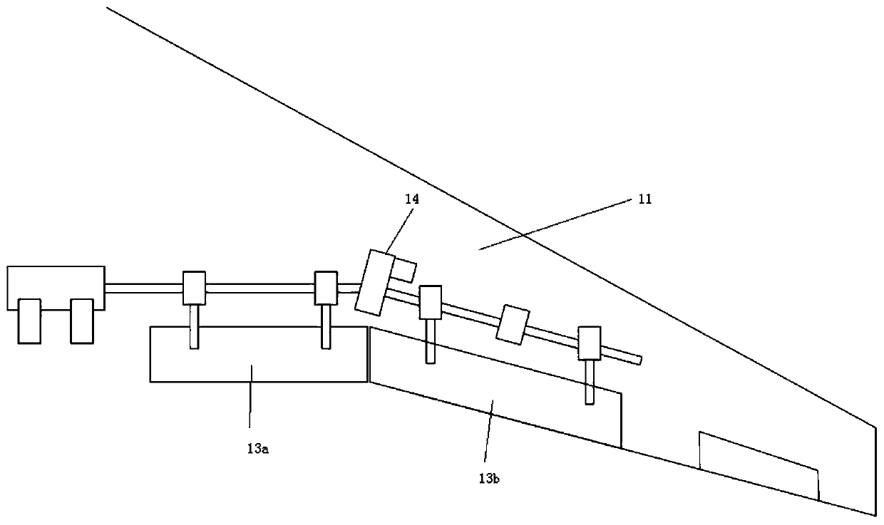
[0118] More specifically, if the kinematic mechanism of the flap is hinged, the flap moves in a circle around the hinge p...

Embodiment approach 3

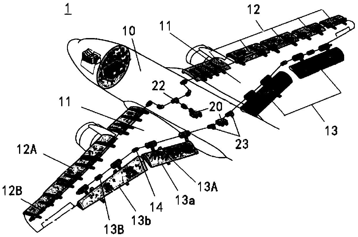
[0142] The aircraft of the present embodiment (embodiment 3) has the function of changing the camber of the wings. Each side flap has a position sensor. Here, it is assumed that the position sensor 146 of the inner flap 13b fails as an example for description.

[0143] In the previous embodiment (Embodiment 1), the electrical characteristics of the two channels of the position sensors on the left and right sides are basically similar, and the output voltage value of the flap surface is basically the same at aerodynamic zero. Therefore, there is no need to establish and use The functional relationship f(x) between the output voltage value of the inclination sensor 170 and the airfoil angle, but in this embodiment (embodiment 3), the electrical characteristics of the two channels of the position sensors on the left and right sides are basically not required. Similarly, at this time, the functional relationship f(x) between the output voltage value of the tilt sensor 170 and the ...


PUM


Abstract

A flap and slat system can still reliably and efficiently detect the wing surface state of an airplane under the condition that a position sensor breaks down. The flap and slat system at least comprises two flap and slat electronic control devices, and one or two position sensors and four inclination sensors, which are arranged on flaps on each side of a left wing and a right wing of the airplanerespectively, namely, two or four position sensors and eight inclination sensors are arranged in total; and the two flap and slat electronic control devices communicate with each other through a CAN bus, and the position sensors are used for detecting the asymmetry of the wing surfaces of the left side wing and the right side wing, and when any one or more of the two or four position sensors breakdown, the inclination sensors are used for replacing the position sensors to detect the asymmetry of the wing surfaces of the left side wing and the right side wing.

Description

technical field [0001] The present invention relates to a flap and slat system, more particularly, relates to a flap and slat system for monitoring and controlling the state of the wing surface of an aircraft when the position sensor of the flap fails. Background technique [0002] Such as figure 1 As shown, a modern large aircraft 1 is provided with a slat 12 at the leading edge of the wing and a flap 13 at the trailing edge of the wing on the left and right wings 11 located on both sides of the main body 10 of the aircraft. The slat 12 and the flap 13 transmit the power from the gear boxes 22, 23 corresponding to the slat 12 and the flap 13 in the power drive device 20, and through respective kinematic mechanisms (the slat kinematic mechanism 12A and the flap motion Mechanism 13A) performs extension and / or swivel movements, respectively. [0003] In addition, at the tip positions of the slats 12 and flaps 13 of the left and right wings 11 (the position away from the side...

Claims


Application Information

Patent Timeline
Patent Type & Authority Applications(China)
IPC IPC(8): B64F5/60B64C9/14B64C9/20
CPCB64C9/14B64C9/20B64F5/60
Inventor 王伟达王晓熠刘锦涛杨志丹徐东光
Owner COMAC
Why Eureka
Try Eureka