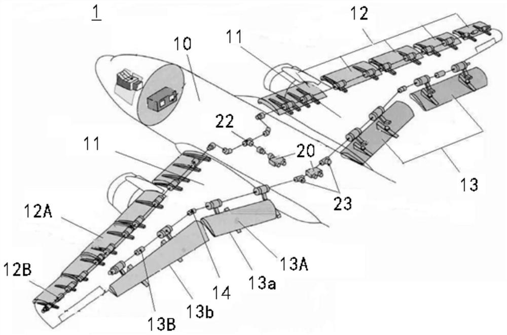
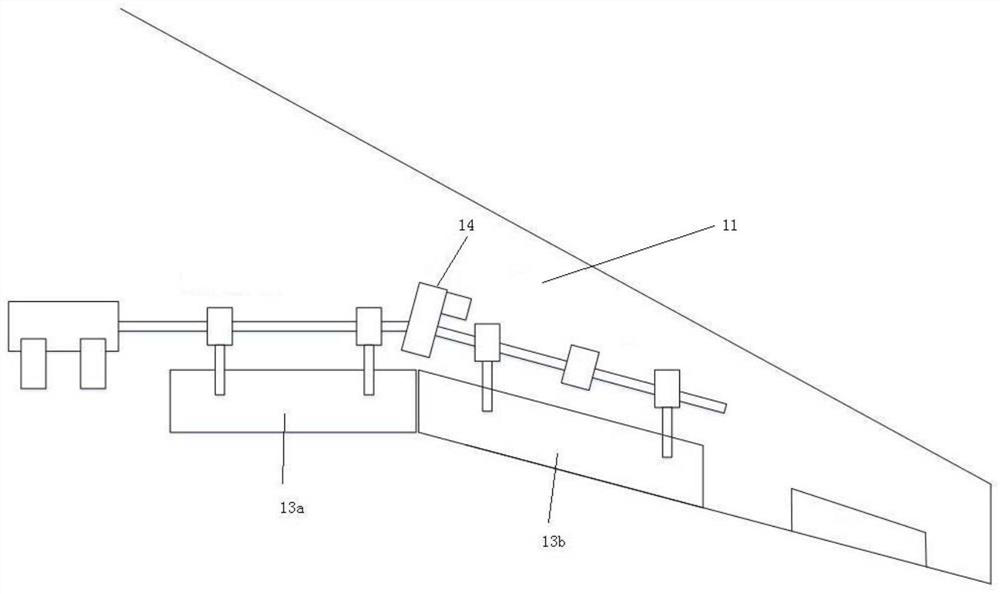
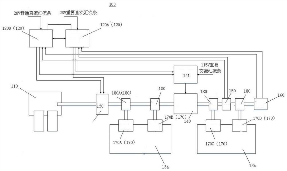
Flap and slat system
A technology of slats and flaps, which is used in aircraft component testing, transportation and packaging, aircraft parts, etc., and can solve problems such as too conservative disposal methods, insufficient use of tilt sensors, and reduced performance and efficiency of flaps and slats.
- Summary
- Abstract
- Description
- Claims
- Application Information
AI Technical Summary
Problems solved by technology
Method used
Image
Examples
Embodiment approach 1
[0093] The aircraft of this embodiment (embodiment 1) does not possess the function of changing the camber of the wing. Each side flap has a position sensor. Here, assume that the position sensor of the left flap fails as an example.
[0094] In this embodiment (Embodiment 1), the electrical characteristics of the two channels of the position sensors on the left and right sides are basically similar, and the output voltage values of the flap surfaces at aerodynamic zero are basically the same.
[0095] In addition, after the electronic adjustment of the flap control system is completed, the output voltage value of channel 1 of the left position sensor is PSU L1RiggingOutput1 , the output voltage value of channel 2 of the left position sensor is PSU L2RiggingOutput , while the output voltage value of channel 1 of the right position sensor is PSU R1RiggingOutput , the output voltage value of channel 2 of the right position sensor is PSU R2RiggingOutput . At this point, the...
Embodiment approach 2
[0116] The aircraft of this embodiment (embodiment 2) does not possess the function of changing the camber of the wing. Each side flap has a position sensor. Here, assume that the position sensor of the left flap fails as an example.
[0117] In the previous embodiment (Embodiment 1), the electrical characteristics of the two channels of the position sensors on the left and right sides are basically similar, and the output voltage value of the flap surface is basically the same at aerodynamic zero. Therefore, there is no need to establish and use The functional relationship f(x) between the output voltage value of the tilt sensor 170 and the airfoil angle. Similarly, at this time, the functional relationship f(x) between the output voltage value of the tilt sensor 170 and the airfoil angle needs to be established, and stored in the slat control computer.
[0118] More specifically, if the kinematic mechanism of the flap is hinged, the flap moves in a circle around the hinge p...
Embodiment approach 3
[0142] The aircraft of the present embodiment (embodiment 3) has the function of changing the camber of the wings. Each side flap has a position sensor. Here, it is assumed that the position sensor 146 of the inner flap 13b fails as an example for description.
[0143] In the previous embodiment (Embodiment 1), the electrical characteristics of the two channels of the position sensors on the left and right sides are basically similar, and the output voltage value of the flap surface is basically the same at aerodynamic zero. Therefore, there is no need to establish and use The functional relationship f(x) between the output voltage value of the inclination sensor 170 and the airfoil angle, but in this embodiment (embodiment 3), the electrical characteristics of the two channels of the position sensors on the left and right sides are basically not required. Similarly, at this time, the functional relationship f(x) between the output voltage value of the tilt sensor 170 and the ...
PUM
 Abstract
Description
Claims
Application Information
 - R&D
- Intellectual Property
- Life Sciences
- Materials
- Tech Scout
- Unparalleled Data Quality
- Higher Quality Content
- 60% Fewer Hallucinations
Browse by: Latest US Patents, China's latest patents, Technical Efficacy Thesaurus, Application Domain, Technology Topic, Popular Technical Reports.
© 2025 PatSnap. All rights reserved.Legal|Privacy policy|Modern Slavery Act Transparency Statement|Sitemap|About US| Contact US: help@patsnap.com


