
C-type wingceltis bar and cross beam end adjustable connecting part

An adjustable, connecting piece technology, applied in the direction of building, building structure, etc., can solve the problems of small adjustable range of connecting piece, unable to adapt to the connection between C-shaped purlins and beams, etc., so as to improve the locking range and reduce the possibility. Effect

Active Publication Date: 2020-07-24
JIANGSU JINHUI CONSTR & INSTALLATION ENG
View PDF9 Cites 2 Cited by
  • Summary
  • Abstract
  • Description
  • Claims
  • Application Information

AI Technical Summary

Problems solved by technology

[0004] The above-mentioned connectors use steel plates instead of bolts to bear the load during the connection process, which improves the connection stability between the C-shaped purlin and the beam. However, in the actual installation process, steel structure buildings usually need to set C-shaped purlins of corresponding sizes according to different strength requirements. and beams, but the adjustable range of the above-mentioned connectors is small, and it cannot adapt to the connection between C-shaped purlins and beams of various sizes, which obviously has limitations

Method used


Image

  • C-type wingceltis bar and cross beam end adjustable connecting part
  • C-type wingceltis bar and cross beam end adjustable connecting part
  • C-type wingceltis bar and cross beam end adjustable connecting part

Examples


Embodiment 1

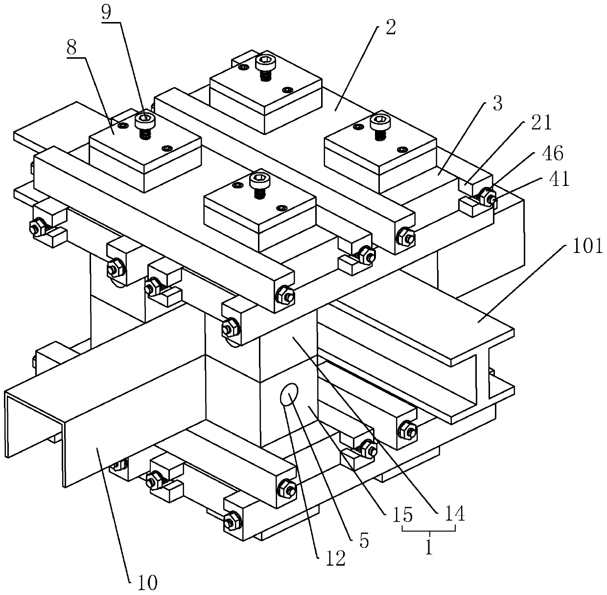
[0037] The invention discloses an adjustable connecting piece at the end of a C-shaped sandalwood bar and a beam. figure 1 , including a positioning column 1 and a limiting plate 2, the positioning column 1 is vertically arranged with four, and the ends of the C-shaped sandalwood bar 10 and the beam 101 are stacked up and down in sequence, and the two are interspersed in the shape of a "ten". Between the positioning columns 1.

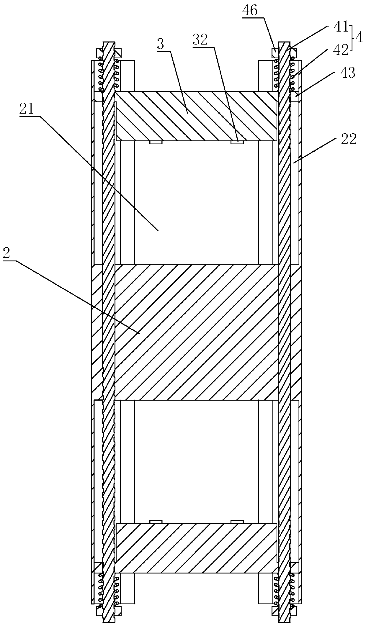
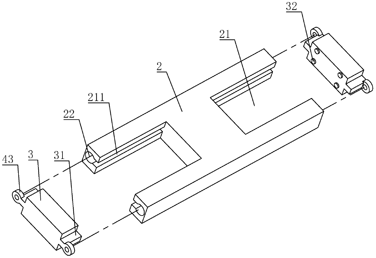
[0038] refer to figure 2 and image 3 , the limiting plate 2 is arranged horizontally, and its two ends are respectively provided with adjustment openings 21 along its length direction, and a locking block 3 which can slide along the length direction of the limiting plate 2 is arranged in the adjusting opening 21 . In order to improve the stability of the locking block 3 during the sliding process, guide sliders 31 are fixedly connected to the two sides of the locking block 3 parallel to the length direction of the limiting plate 2, and the adjustment...

Embodiment 2

[0057] The difference between this embodiment and Embodiment 1 lies in that the locking component 4 is different. refer to Figure 8 , in this embodiment, the locking assembly 4 includes a positioning screw 44 and a deadlock nut 45, the positioning screw 44 is fixedly connected to the side of the positioning column 1 facing the locking block 3, and the locking block 3 is provided with a positioning screw 44 Through the through hole, the deadbolt nut 45 is threadedly connected to the shank where the positioning screw 44 passes through the locking block 3 . After the locking block 3 abuts against the positioning column 1, the positioning screw 44 passes through the perforation, and the staff screw-connects the locking nut 45 on the positioning screw 44, and through the locking of the locking nut 45, the positioning column is realized. 1 and the connection between the locking block 3.


PUM


Abstract

The invention discloses a C-type wingceltis bar and cross beam end adjustable connecting part. The C-type wingceltis bar and cross beam end adjustable connecting part comprises positioning columns andlimiting plates, the four positioning columns are vertically mounted, a C-type wingceltis bar and the end of a cross beam are sequentially stacked up and down, and are interspersed in among the fourpositioning columns in a cross manner, the limiting plates are horizontally mounted, the two ends of the limiting plates are provided with adjusting openings in the length direction, locking blocks sliding in the length direction of the limiting plates are mounted in the adjusting openings, the four limiting plates are mounted on the top ends and the bottom ends of the positioning columns, the four limiting plates are arranged in sequence end to end in a rectangular manner, the adjusting openings in the two ends of the limiting plates are arranged in the ends of the two adjacent positioning columns in a sleeving manner, the locking blocks tightly abut against the positioning columns, and locking assemblies are mounted on the locking blocks. The adjustable connecting part has the advantagesof being suitable for C-type wingceltis bars and cross beams of multiple specification sizes and the large in locking range.

Description

technical field [0001] The invention relates to a steel structure building, in particular to an adjustable connecting piece at the end of a C-shaped sandal bar and a beam. Background technique [0002] Steel structure buildings are structures composed of steel materials and are one of the main types of building structures. The steel structure is mainly composed of beam steel, steel column, steel truss and other components made of section steel and steel plate. Because of its light weight and easy construction, steel structures are widely used in large factories, venues, super high-rises and other fields. [0003] In steel structure buildings, purlins, beams and connections often appear, and the current Chinese patent publication number CN108331179A discloses a connector for fastening C-shaped purlins and beams, including C-shaped purlins, beams, upper half locks The clamping device, the lower half locking device and the fixed insert block, the C-shaped purlin is set on the...

Claims


Application Information

Patent Timeline
Patent Type & Authority Applications(China)
IPC IPC(8): E04B1/58
CPCE04B1/5812E04B1/5818
Inventor 郭小叶王干一宗占平杨信缪泽华
Owner JIANGSU JINHUI CONSTR & INSTALLATION ENG
Learn More