Shield transverse moving station crossing method

A technology of passing stations and shielding, which is applied in earth-moving drilling, mining equipment, tunnels, etc., can solve the problems of inconvenient operation, low construction efficiency, and great difficulties, and achieves the improvement of construction efficiency, cost saving, and material reduction. Effect

Inactive Publication Date: 2020-07-24
CHINA RAILWEY ENG SERVICE CO LTD
View PDF7 Cites 1 Cited by
  • Summary
  • Abstract
  • Description
  • Claims
  • Application Information

AI Technical Summary

Problems solved by technology

[0005] Aiming at the problems in the prior art that it is difficult to translate the shield machine horizontally by the translational passing device, and the operation is inconvenient and the construction efficiency is low, the present invention provides a method for shield tunneling translational movement, the purpose of which is to: reduce the shield machine Reduce the difficulty of horizontal translation of the machine and improve construction efficiency

Method used


Image

  • Shield transverse moving station crossing method
  • Shield transverse moving station crossing method
  • Shield transverse moving station crossing method

Examples


Embodiment 1

[0060] A method for shield tunneling translation, comprising the following steps:

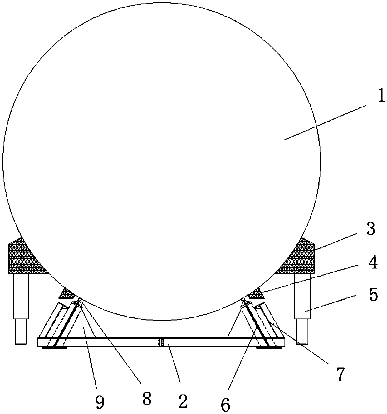
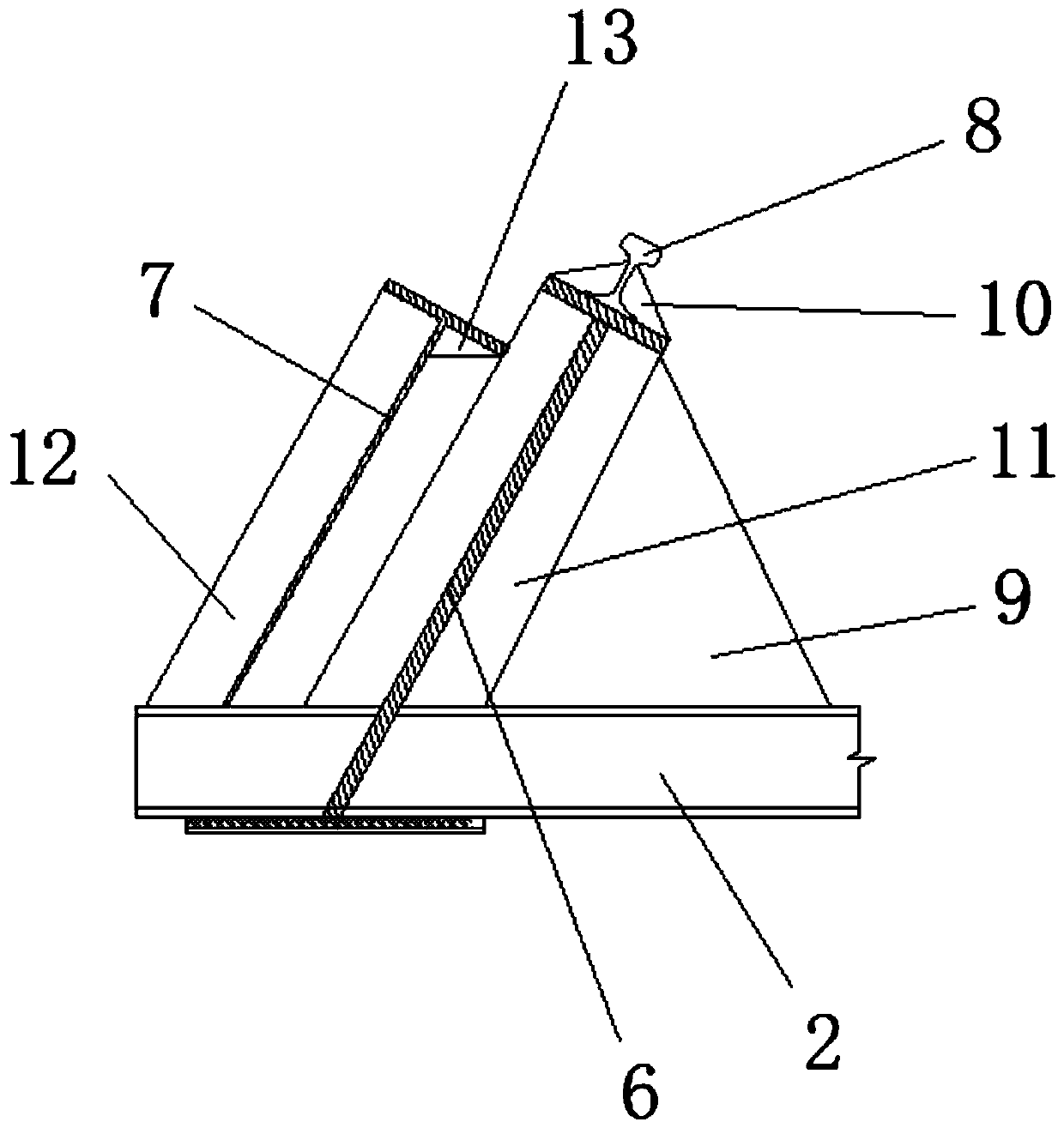
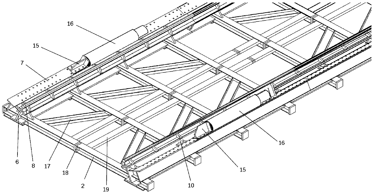
[0061] S1: Construction preparation: install the bracket 20, set the bracket traverse hydraulic cylinder 14 on the side of the bracket 20, weld several first corbels 3 and several second corbels 4 on both sides of the lower part of the shield machine 1 , the lower end of the first corbel 3 is provided with a lifting hydraulic cylinder 5, and the side of the second corbel 4 is a longitudinal hydraulic cylinder 16 with the same axial direction as the shield machine 1;

[0062] S2: placing the shield machine 1 on the bracket 20;

[0063] S3: Horizontal movement of the shield machine 1: firstly control the elongation of the lifting hydraulic cylinder 5 to lift the shield machine 1; then control the extension of the bracket lateral movement hydraulic cylinder 14 to make the bracket 20 translate to the right (for the convenience of description, this The example only takes Figure 6-9 The direction ...

Embodiment 2

[0084] A method for shield tunneling translation, comprising the following steps:

[0085] S1: Construction preparation: install the bracket 20, set the bracket traverse hydraulic cylinder 14 on the side of the bracket 20, weld several first corbels 3 and several second corbels 4 on both sides of the lower part of the shield machine 1 , the lower end of the first corbel 3 is provided with a lifting hydraulic cylinder 5, and the side of the second corbel 4 is a longitudinal hydraulic cylinder 16 with the same axial direction as the shield machine 1;

[0086] S2: placing the shield machine 1 on the bracket 20;

[0087] S3: Horizontal movement of the shield machine 1: firstly control the elongation of the lifting hydraulic cylinder 5 to lift the shield machine 1; then control the extension of the bracket lateral movement hydraulic cylinder 14 to make the bracket 20 translate laterally; then control the shield machine 1 The lifting hydraulic cylinder 5 on one side is shortened so...


PUM


Abstract

The invention discloses a shield transverse moving station crossing method, and belongs to the technical field of shield construction. The problems that in the prior art, a transverse moving station crossing device is large in transverse moving difficulty of a shield tunneling machine, operation is not convenient, and construction efficiency is low are solved. The method comprises the following steps of S1, construction preparation; S2, putting of the shield tunneling machine (1) on a bracket (20); S3, transverse moving of the shield tunneling machine (1); S4, longitudinal moving of the shieldtunneling machine (1); and S5, in-place operation of the shield tunneling machine (1). Through cooperation of a lifting hydraulic cylinder and a bracket transverse moving hydraulic cylinder, transverse moving of the shield tunneling machine can be conveniently carried out, the operation process is simple, construction efficiency can be improved, construction cost is saved, and the method is suitable for shield station passing construction.

Description

technical field [0001] The invention belongs to the technical field of shield tunneling, and in particular relates to a method for shield tunneling to move over stations in translation. Background technique [0002] With the development of the city, the urban underground rail transit is becoming more and more mature, and the shield tunneling method is currently the safest tunnel construction method in tunnel construction. In subway construction, there are many stations and short intervals. In most cases, the shield machine needs to pass through one or more stations. Due to the large size of the shield machine, passing the station is a difficult problem in shield tunneling construction. [0003] At present, the traditional shield tunneling methods mainly include dismantling, hoisting and moving. Dismantling and lifting requires frequent hoisting in and out, as well as dismantling, secondary assembly, and secondary commissioning of the shield machine and supporting equipment,...

Claims


Application Information

Patent Timeline
Patent Type & Authority Applications(China)
IPC IPC(8): E21D9/06
CPCE21D9/06
Inventor 张轩陈申强白杰龚晓林申德芳晏立忠谢飞邢杰博周全洪余乐
Owner CHINA RAILWEY ENG SERVICE CO LTD
Why Eureka
Try Eureka