

Method for constructing end wall of subway station in sandy gravel stratum
A technology for subway stations and construction methods, which is applied in underground chambers, earth-moving drilling, wellbore lining, etc., can solve problems affecting shield construction safety, damage to station end wall enclosures and waterproofing membranes, etc., to ensure waterproofing. performance and safety
- Summary
- Abstract
- Description
- Claims
- Application Information
AI Technical Summary
Problems solved by technology
Method used
Image

Examples
Embodiment Construction
[0022] In order to ensure that the construction of the pipe shed does not destroy the airtightness of the waterproof coiled layer, the present invention divides the end wall into an inner layer and an outer layer, and the waterproof coiled layer is arranged between the inner and outer layers. The outer layer is divided into a pre-casting belt and a post-casting belt, which is convenient for pipe shed construction and waterproof membrane lapping.
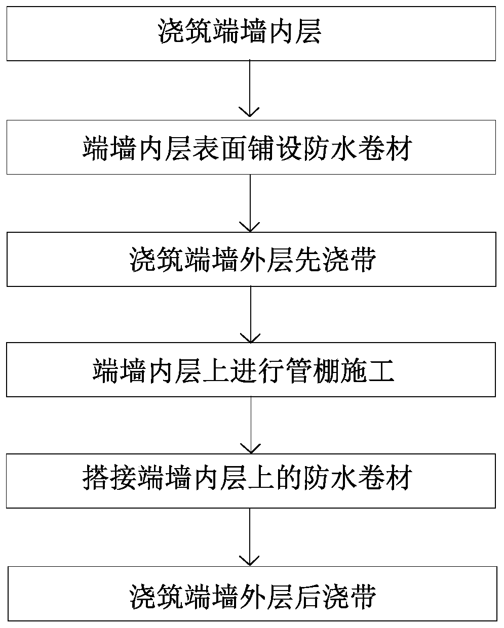
[0023] Construction process such as figure 1 As shown, pour the inner layer of the end wall first, lay the waterproof coiled material on the inner layer of the end wall, then pour the outer layer and pour the belt first, leave the construction position of the pipe shed, carry out the construction of the pipe shed, overlap the dense waterproof coil layer, and finally pour the outer wall Post-pouring tape. The specific construction steps are as follows:
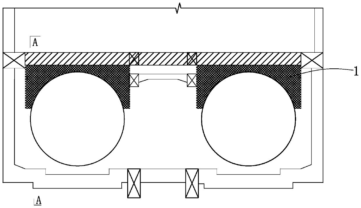
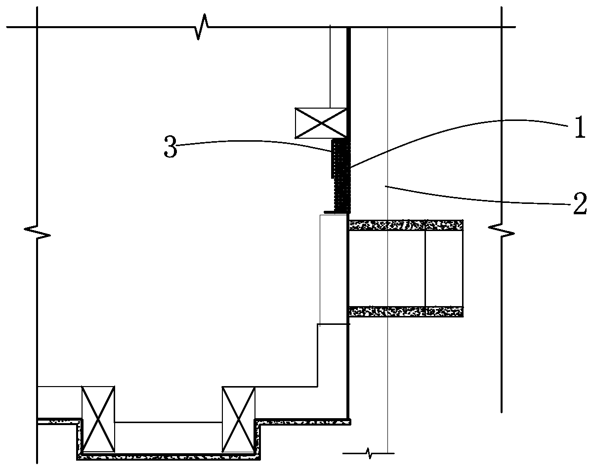
[0024] (1) if figure 2 , image 3 As shown, the inner layer 1 of the end wal...
PUM
| Property | Measurement | Unit |
|---|---|---|
| Thickness | aaaaa | aaaaa |
| Thickness | aaaaa | aaaaa |
Abstract
Description
Claims
Application Information