
A heating device for dental equipment water

A heating device and equipment technology, applied in the field of medical equipment, can solve the problems of no stirring function, cumbersome heating process, uneven cooling and heating of water, etc., and achieve the effect of convenient heating, beneficial to treatment, and uniform heating and cooling

Inactive Publication Date: 2021-09-07
XIANGYA HOSPITAL CENT SOUTH UNIV
View PDF0 Cites 0 Cited by
  • Summary
  • Abstract
  • Description
  • Claims
  • Application Information

AI Technical Summary

Problems solved by technology

[0004] The purpose of the present invention is to solve the shortcomings of the existing equipment without a certain stirring function, uneven cooling and heating of the water, and the heating process is cumbersome and wastes unused water, and proposes a water heating device for dental equipment

Method used


Image

  • A heating device for dental equipment water
  • A heating device for dental equipment water
  • A heating device for dental equipment water

Examples


Embodiment 1

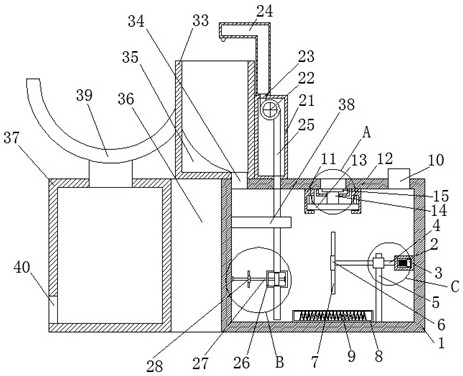
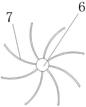
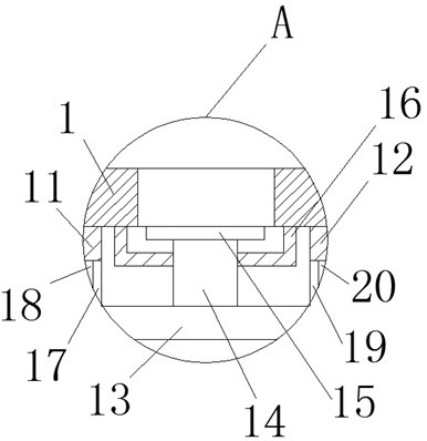
[0027] refer to Figure 1-5 , a water heating device for dental equipment, comprising an incubator 1, a drive motor 3 is fixedly installed on one side of the incubator 1, an end of a drive shaft 4 is fixedly installed on the output shaft of the drive motor 3, and the drive shaft 4 rotates Installed on the bottom inner wall of the incubator 1, the other end of the drive shaft 4 is fixedly installed with a first connecting plate 6, on the first connecting plate 6 are fixedly installed several stirring blades 7, and the bottom of the incubating box 1 is fixedly installed with a heating box 8. A resistance wire 9 is fixedly installed in the heating box 8, a water injection port 10 is opened on the top of the incubator 1, and a first mounting plate 11 and a second mounting plate 12 are symmetrically fixed on the inner wall of the top of the incubating box 1. The same floating board 13 is slidably installed on the board 11 and the second mounting board 12, the second connecting boar...

Embodiment 2

[0038] refer to Figure 1-5, a water heating device for dental equipment, comprising an incubator 1, the setting of the incubator 1 enables the heated water to be kept warm for a long time for use, and a drive motor 3 is fixedly installed on one side of the incubator 1 by welding, One end of the drive shaft 4 is fixedly installed by welding on the output shaft of the drive motor 3, and the drive shaft 4 is rotatably installed on the bottom inner wall of the incubator 1, and the other end of the drive shaft 4 is fixedly installed with the first connecting plate 6 by welding. A connecting plate 6 is fixedly installed with several stirring blades 7 by welding. The installation of the stirring blades 7 makes the heating of the water more uniform. The bottom of the incubator 1 is fixedly installed with a heating box 8 by welding. The resistance wire 9 is fixedly installed by welding, and the resistance wire 9 is connected in the circuit to achieve the purpose of heating water. The ...


PUM


Abstract

The invention belongs to the technical field of medical devices, in particular to a water heating device for dental equipment, aiming at the problems that the existing equipment does not have a certain stirring function, the outlet water is cold and hot, the heating process is cumbersome, and unused water is wasted. The following scheme is proposed now, which includes an incubator, a drive motor is fixedly installed on one side of the incubator, an end of a drive shaft is fixedly installed on the output shaft of the drive motor, and the drive shaft is rotatably mounted on the bottom inner wall of the incubator , the other end of the drive shaft is fixedly installed with a first connecting plate, a number of stirring blades are fixedly installed on the first connecting plate, a heating box is fixedly installed at the bottom of the incubator, a resistance wire is fixedly installed in the heating box, and the top of the incubator A water injection port is provided. The invention is more convenient to use for heating, and does not waste, and the water taken out is evenly cooled and hot, and does not cause damage to the patient, and is more beneficial to the treatment of the patient.

Description

technical field [0001] The invention relates to the technical field of medical devices, in particular to a water heating device for dental equipment. Background technique [0002] In dental treatment, it is necessary to use water heated to a certain temperature to rinse the patient's mouth. Therefore, it is necessary to heat the water to a suitable temperature through a heating device. At present, the heating device for this type of application uses metal materials as the shell, and heats the water inside after the internal resistance heating rod is energized. In addition, during the dental treatment process, mouthwash cleaning is very frequent, so it is very important to control the water temperature. If it is too cold, it will be irritated, if it is too hot, it will cause burns. [0003] However, most of the existing devices heat the water outlet, which is cumbersome to use and is easy to burn. At the same time, most of the equipment does not have a certain stirring func...

Claims


Application Information

Patent Timeline
Patent Type & Authority Patents(China)
IPC IPC(8): F24H1/20F24H9/00F24H9/16F24H9/18F24H9/20
CPCF24H1/202F24H9/0005F24H9/0015F24H9/16F24H9/1818F24H9/2021
Inventor 陈洋邓美玲高峰
Owner XIANGYA HOSPITAL CENT SOUTH UNIV
Learn More