
Annular experimental device for simulating wheel-rail and bow-net contact high-frequency vibration state

A high-frequency vibration and experimental device technology, used in measurement devices, vibration testing, machine/structural component testing, etc., can solve problems such as the inability to simulate the contact state of wheels and rails, improve scientific research progress, reduce simulation costs, and shorten experiments. effect of cycles

Active Publication Date: 2020-07-24
SHANGHAI UNIV OF ENG SCI
View PDF7 Cites 2 Cited by
  • Summary
  • Abstract
  • Description
  • Claims
  • Application Information

AI Technical Summary

Problems solved by technology

[0006] The purpose of the present invention is to overcome the defect that the existing technology cannot simulate the wheel-rail contact state, and provide a ring-shaped experimental device that can truly simulate the wheel-rail and pantograph-catenary contact state. , extend the track overhaul period, reduce the workload of line maintenance, ensure the safe and economical operation of heavy-duty, high-speed trains, and reduce the occurrence and development of corrugation, providing new experimental means

Method used


Image

  • Annular experimental device for simulating wheel-rail and bow-net contact high-frequency vibration state

Examples


Embodiment 1

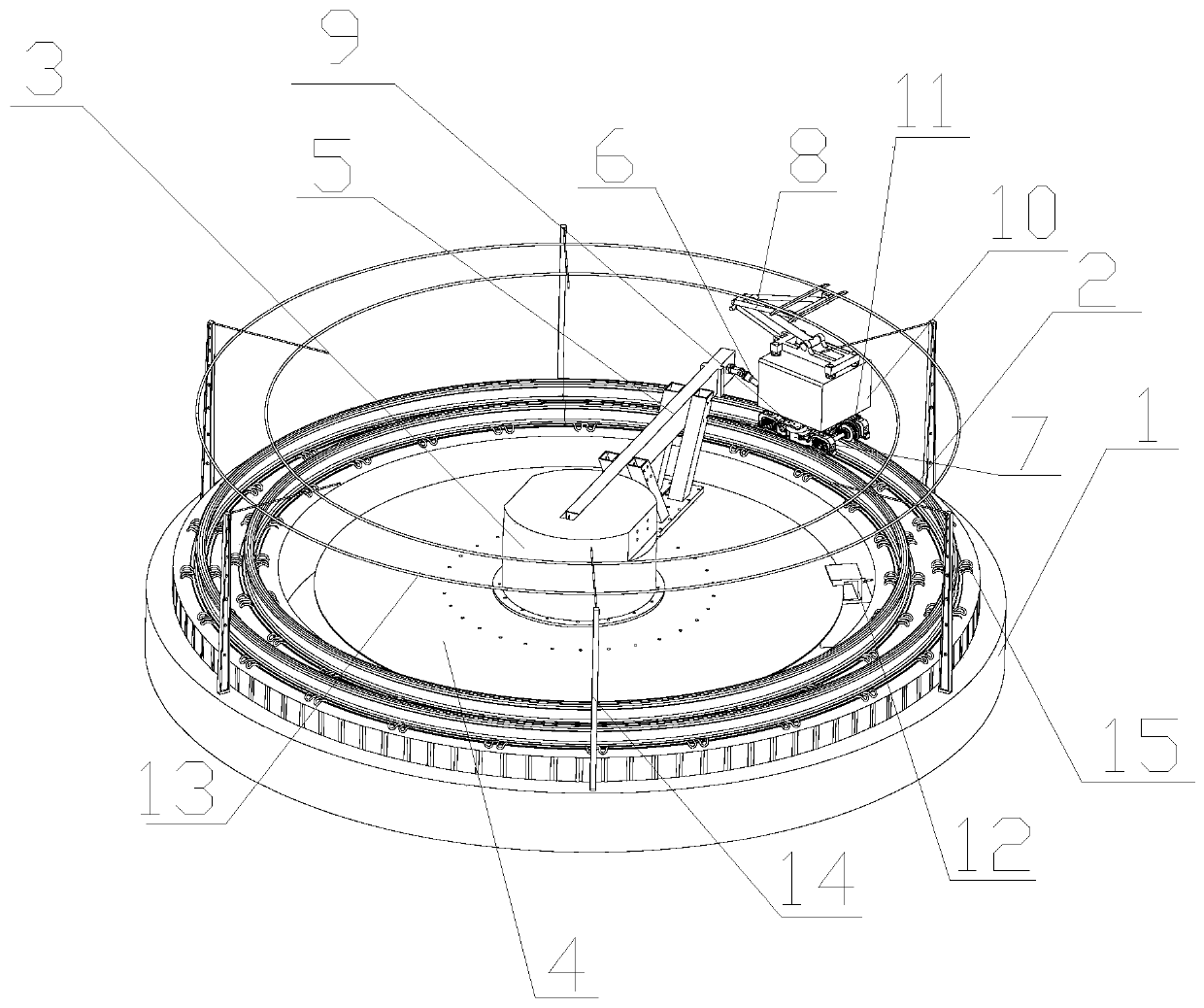
[0038] A ring-shaped experimental device for simulating the high-frequency vibration state of wheel-rail and pantograph-catenary contact, such as figure 1 As shown, it includes a circular track 2 arranged horizontally;

[0039] The ring track 2 is a circular track with a smooth transition as a whole, and it is fixed on the track bed plate 1 by an elastic fastener 15. An experimental train is arranged on the ring track 2, and an annular traction device for pulling the test train is arranged in the center of the ring track. The annular traction device is connected with the experimental train through the pivoting arm 5 and the coupler 6, and the experimental train moves along the circular track 2 under the action of the annular traction device;

[0040] The annular traction device includes a drive mechanism 3, a gear disc 4 and a hydraulic brake 12. The drive mechanism 3 is arranged in the center of the gear disc 4. The drive mechanism 3 includes a motor and a reducer connected t...

Embodiment 2

[0048] A ring-shaped experimental device for simulating the high-frequency vibration state of wheel-rail and pantograph-catenary contact. Its structure is basically the same as that of Embodiment 1. The difference lies in the power supply mode of the traction motor of the bogie. Electricity, while the cable network is powered by the converter equipment, and the speed of the traction motor of the bogie is controlled by controlling the converter equipment.


PUM


Abstract

The invention discloses an annular experimental device for simulating a wheel-rail and bow-net contact high-frequency vibration state. The annular experimental device comprises an annular rail which is horizontally arranged and is in smooth transition as a whole, wherein an experimental train is arranged on the annular rail; an annular traction device for dragging the experimental train is arranged in the center of the annular rail; the annular traction device is connected with the experimental train through a rotating arm and a coupler; the experimental train moves along the annular rail under the action of the annular traction device; the experimental train comprises a train body, a bogie, a wheel pair and a pantograph; the pantograph is in contact with a cable network arranged above theannular rail; a bogie traction motor for driving the wheel pair is mounted on the bogie; and an output shaft of the bogie traction motor is connected with the wheel pair. According to the annular experimental device, a creeping phenomenon caused by train operation is simulated through two sets of power systems, namely the annular traction device and the bogie traction motor, and the wheel-rail contact state is really simulated; and compared with a complete simulation scene, the annular experimental device has the advantages that the simulation condition is greatly reduced, the simulation costis reduced, and the application prospect is good.

Description

technical field [0001] The invention belongs to the technical field of track simulation test, and relates to a ring-shaped experimental device for simulating the high-frequency vibration state of wheel-rail and pantograph-catenary contact, in particular to a device capable of simulating wheel-rail and pantograph-catenary contact in a laboratory environment in a manner close to reality state of the experimental device. Background technique [0002] With the increase of operation time, the railway track will have a certain regularity and periodical wear in the longitudinal direction on some parts of the rail top surface, which is similar to the wave shape. This phenomenon is called track wave wear, or wave wear for short. Track corrugation is one of the main causes of track damage, wheel-rail vibration and noise. [0003] Corrugation can generally be divided into short-wavelength corrugation and long-wavelength corrugation. The former has a wavelength of 20-80mm and a wave de...

Claims


Application Information

Patent Timeline
Patent Type & Authority Applications(China)
IPC IPC(8): G01M17/08G01M7/02
CPCG01M17/08G01M7/00
Inventor 尧辉明王安斌高晓刚翟字波许牧天
Owner SHANGHAI UNIV OF ENG SCI
Learn More