Tensile property detection device for cable processing

A detection device and anti-stretching technology, applied in the measurement device, using stable tension/pressure to test the strength and strength characteristics of materials, etc., can solve the problems of low efficiency and poor detection accuracy, and achieve high detection efficiency and convenient use. , the effect of uniform force

Active Publication Date: 2020-07-24
涌纬集团股份有限公司
View PDF3 Cites 4 Cited by
  • Summary
  • Abstract
  • Description
  • Claims
  • Application Information

AI Technical Summary

Problems solved by technology

[0004] The purpose of the present invention is to solve the problems of low efficiency and poor detection accuracy in the prior art, and propose a tensile performance detection device for cable processing

Method used


Image

  • Tensile property detection device for cable processing
  • Tensile property detection device for cable processing
  • Tensile property detection device for cable processing

Examples


Embodiment 1

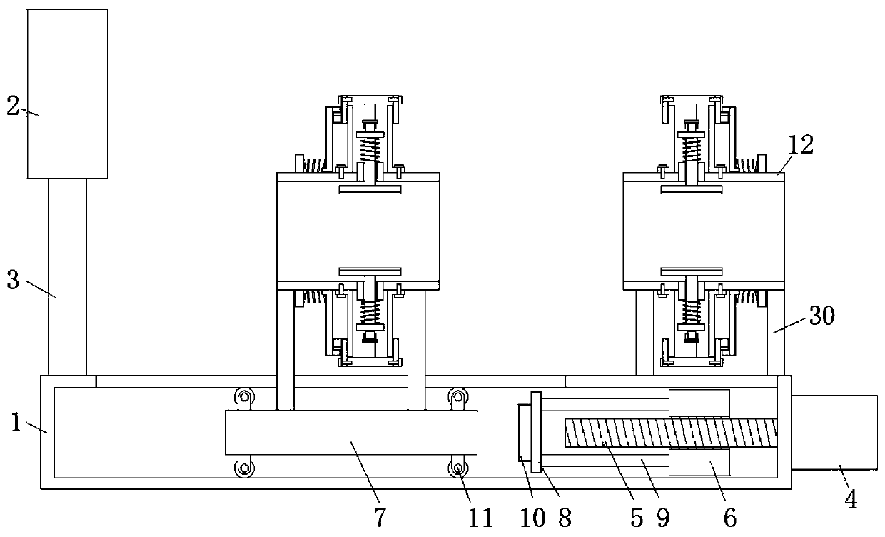
[0026] Reference Figure 1-4 , A tensile resistance testing device for cable processing, comprising a bottom box 1, an organic meter 2 is set vertically above the top end of the bottom box 1, and a meter 2 is set between the bottom side of the meter 2 and the top side of the bottom box 1. Mounting frame 3, the vertical side of the bottom box 1 is fixedly installed with a motor 4 by bolts, the output shaft of the motor 4 is connected with a threaded rod 5, and the bottom box 1 is horizontally slidingly connected with a sliding plate 6 and a sliding plate 2. 6 and the second slide plate 7 are arranged in parallel, and the plate body of the slide plate 6 is provided with a threaded through hole, and the threaded rod 5 is threaded through the threaded hole. The side of the slide plate 6 and the slide plate 2 7 close to each other is provided with a mounting plate 8 A linkage arm 9 is fixedly connected between one side of the mounting plate 8 and the sliding plate 6; the pressure se...

Embodiment 2

[0029] Such as Figure 1-4 As shown, this embodiment is basically the same as Embodiment 1. Preferably, the top side of the bottom box 1 is provided with a top hole, and one of the support frames 30 passes through the top hole.

[0030] In this embodiment, the wire barrel 12 erected by one support frame 30 is kept relatively fixed with the bottom box 1, and the wire barrel 12 erected by the other support frame 30 moves horizontally under the operation of the motor 4, thereby pulling the cable .

Embodiment 3

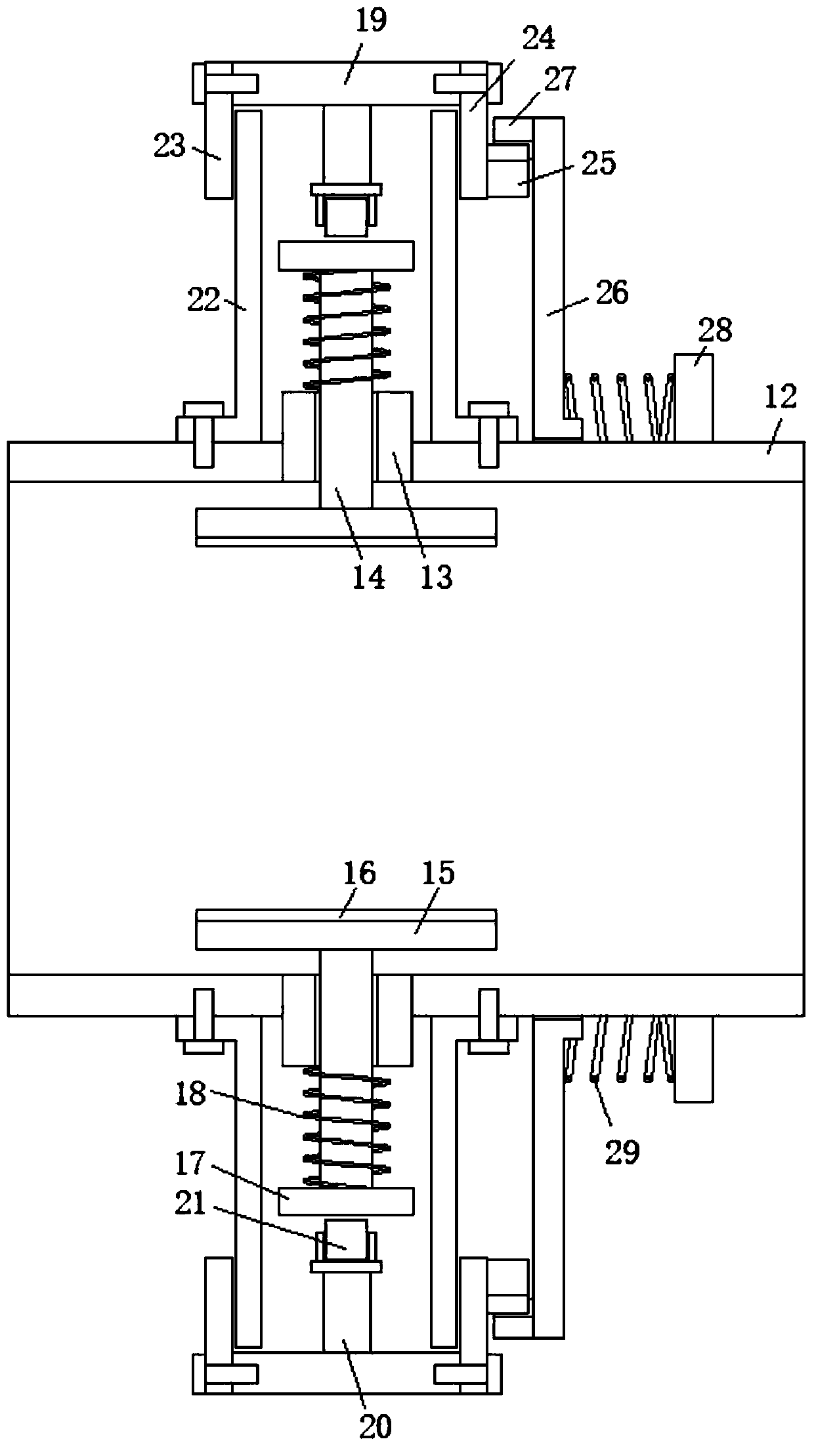
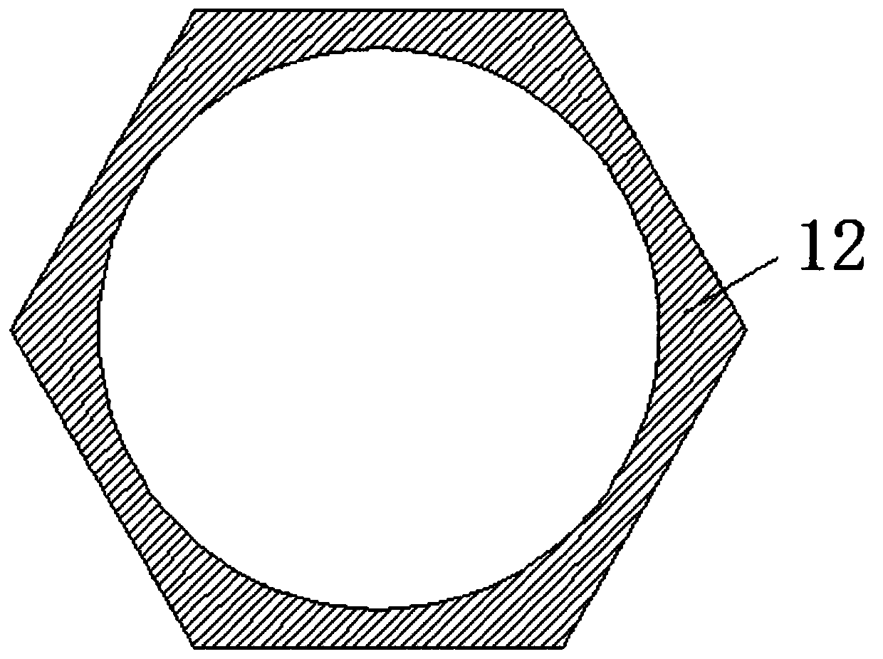
[0032] Such as Figure 1-4 As shown, this embodiment is basically the same as Embodiment 1. Preferably, the inner side of the slip ring 26 is a polygonal structure, and the inner wall of the slip ring 26 is connected to the outer side of the wire barrel 12 in sliding contact.

[0033] In this embodiment, after people control the slip ring 26 to move horizontally with one hand, the second gear ring 27 and the gear ring one 25 are disengaged, and at the same time, the slip ring 26 restricts the rotation of the spool 12 through the polygonal structure. When the other hand is used to rotate the control ring 19, the wire barrel 12 and the control ring 19 rotate relative to each other, so that the positioning plate 15 is enclosed and fixed for the cable.


PUM


Abstract

The invention discloses a tensile property detection device for cable processing. The device comprises a bottom box, a machine meter is vertically arranged above one end of the top of the bottom box,a mounting frame is arranged between the bottom side of the machine meter and the top side of the bottom box, a motor is fixedly mounted on the vertical side of the bottom box through a bolt, an output shaft of the motor is in transmission connection with a threaded rod, a first sliding plate and a second sliding plate are horizontally and slidably arranged in the bottom box in a connection mode,the first sliding plate and the second sliding plate are arranged in parallel, a threaded through hole is formed in a plate body of the first sliding plate, a threaded rod penetrates through the threaded through hole in a threaded mode, a mounting plate is arranged on the sides, close to each other, of the first sliding plate and the second sliding plate, a linkage arm is fixedly arranged betweenone side of the mounting plate and the first sliding plate in a connection mode, and a pressure sensor is fixedly mounted on the side, close to the second sliding plate, of the mounting plate. The device realizes the tensile detection of wires and cables, has high detection efficiency and high detection precision, is convenient to use, and meets use requirements of people in production and life.

Description

Technical field [0001] The invention relates to the technical field of cable processing equipment, in particular to a tensile resistance testing device for cable processing. Background technique [0002] A cable is usually a rope-like cable formed by twisting several or several groups of wires (at least two in each group). Each group of wires is insulated from each other and is often twisted around a center. Highly insulating cover layer. The cable has the characteristics of internal electricity and external insulation. Cables include power cables, control cables, compensation cables, shielded cables, high temperature cables, computer cables, signal cables, coaxial cables, fire-resistant cables, marine cables, mining cables, aluminum alloy cables, and so on. They are composed of single or multiple strands of wires and insulating layers, which are used to connect circuits and electrical appliances. [0003] In the process of using existing cables, in order to meet different use e...

Claims


Application Information

Patent Timeline
Patent Type & Authority Applications(China)
IPC IPC(8): G01N3/02G01N3/04G01N3/08
CPCG01N3/02G01N3/04G01N3/08
Inventor 李国宝郑桂东尹华顺
Owner 涌纬集团股份有限公司
Why Eureka
Try Eureka