
Power box for municipal engineering

A power box and engineering technology, applied in the direction of electrical components, substation/power distribution device shell, substation/switch layout details, etc., can solve the problem of power box power supply line damage and short circuit, etc., to reduce the repelling effect and avoid messy strings everywhere Effect

Active Publication Date: 2020-07-24
湛江市鼎奕电力科技有限公司
View PDF8 Cites 1 Cited by
  • Summary
  • Abstract
  • Description
  • Claims
  • Application Information

AI Technical Summary

Problems solved by technology

[0003] Since there are many rats in spring and summer, especially in areas such as garbage dumps, the activity of mice is more frequent, so that the power box installed near the garbage dump is likely to have mice enter the interior through the heat dissipation vents that communicate with the outside world, resulting in damage to the inside of the power box. The power supply line was bitten off by a mouse and there was a damaged short circuit

Method used


Image

  • Power box for municipal engineering
  • Power box for municipal engineering
  • Power box for municipal engineering

Examples


Embodiment 1

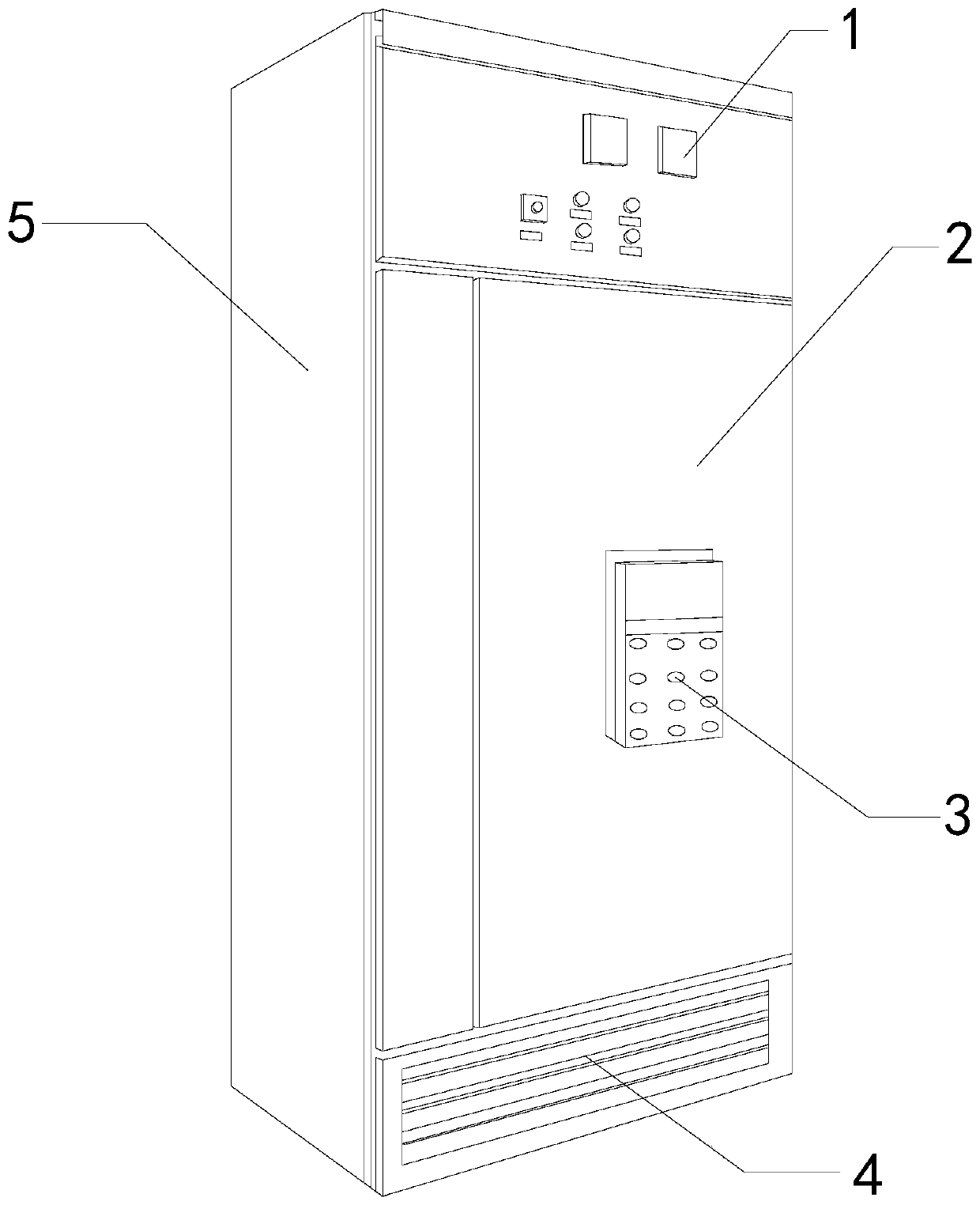
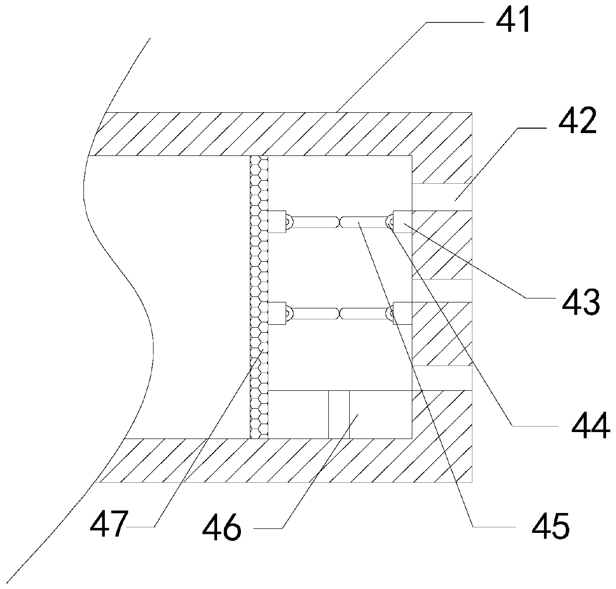
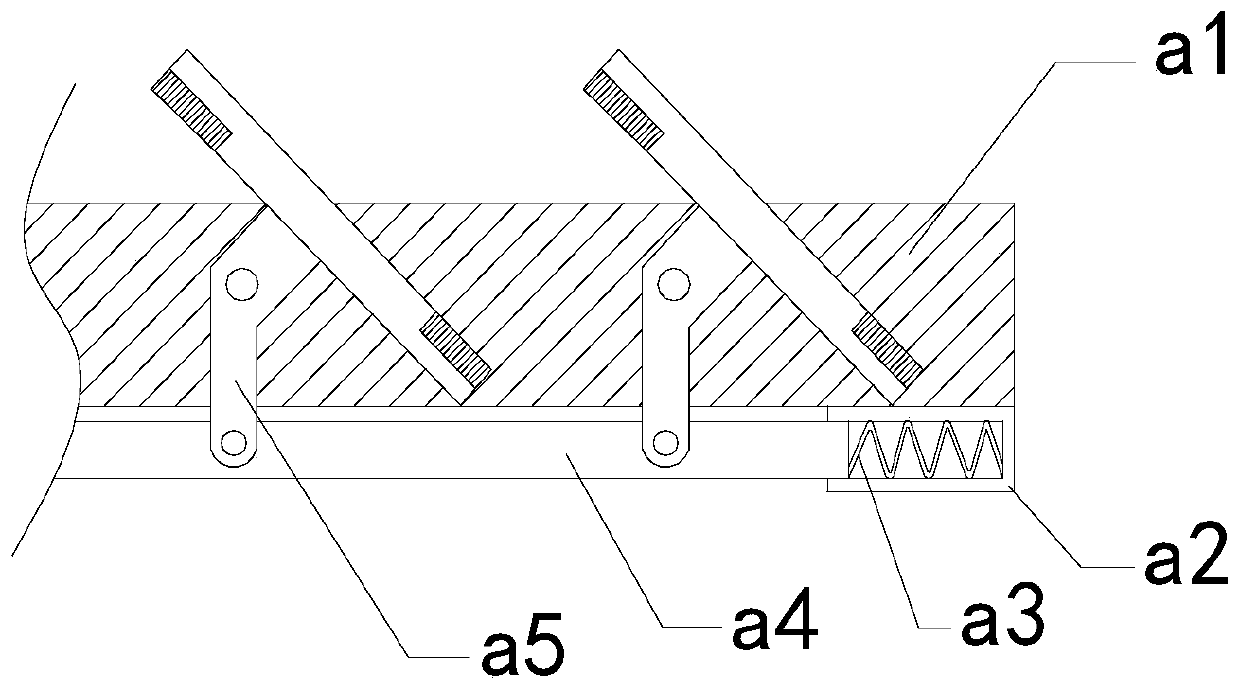
[0029] For example figure 1 -example Image 6 Shown:

[0030] The invention provides a power box for municipal engineering, its structure includes an alarm 1, a box door 2, a control panel 3, a radiator 4, and a power box 5, the alarm 1 is embedded and connected to the power box 5, and the box The door 2 is hingedly connected to the power box 5 , the back surface of the control panel 3 is attached to the surface of the box door 2 , and the radiator 4 is welded to the bottom of the power box 5 .

[0031] Wherein, the heat sink 4 includes a shell 41, a heat dissipation port 42, a fixed block 43, a rebound ring 44, an opening and closing plate 45, an expelling mechanism 46, and a ventilating plate 47, and the heat dissipation port 42 and the shell 41 are an integral structure, so The fixed block 43 is provided with four, and the two on the right end are connected with the inner wall of the casing 41, and the two on the left end are embedded in the right side of the air-permeabl...

Embodiment 2

[0039] For example Figure 7 -example Figure 9 Shown:

[0040] Wherein, the expelling mechanism 46 includes a housing 461, an expelling vane 462, a movable shaft 463, and an outlet 464. The expelling vane 462 is embedded with the movable shaft 463, and the movable shaft 463 is engaged with the bottom of the inner wall of the housing 461. Combined, the outlet 464 and the housing 461 are an integrated structure, and the expelling blades 462 are provided with eight, and are distributed in a circle on the movable shaft 463, and the rats that fall between the expelling blades 462 are dispelled when running. Drive blade 462 thrust, can make it rotate, until mouse is expelled from outlet 464.

[0041] Wherein, the expulsion blade 462 includes a telescopic plate c1, a blocking piece c2, and a cover plate c3, the telescopic plate c1 is matched with the inner wall of the cover plate c3, and there are two blocking pieces c2, and one of them is embedded The outer surface of the telesc...


PUM


Abstract

The invention discloses a power box for municipal engineering. The power box structurally comprises an alarm, a box door, a control panel, a radiator and a power box. The alarm is embedded and fixedlyconnected with the power box; the box door is hinged with the power box; a back surface of the control panel is attached to a surface of the box door; and the radiator is welded at a bottom end of the power box. A mouse can easily enter the power box through a heat dissipation opening in the radiator. Through cooperation of an opening and closing plate and an expelling mechanism, the above situation can be effectively prevented; a condition that the mouse enters the power box through the heat dissipation opening so that lines in the power box are bitten by the mouse is avoided; and due to a fact that the mouse falling from the opening and closing plate is collected through the expelling mechanism, if the mouse stay in the expelling mechanism for a long time, unnecessary pollution can be caused to an inner portion of the expelling mechanism, and through cooperation of expelling blades and a movable shaft, the problem can be effectively solved.

Description

technical field [0001] The invention relates to the field of electric boxes, in particular to an electric box for municipal engineering. Background technique [0002] The power box is mainly a device for distributing electric energy. It is a control center for rationally distributing electric energy to power supply lines, and it can intuitively monitor the use status of power supply and testing circuits. It is a common device in outdoor public places. Based on the above description, the inventor It is found that the existing electric box for municipal engineering mainly has the following deficiencies, for example: [0003] Because there are more rats in spring and summer, especially in areas such as garbage dumps, the activity of mice is more frequent, so that the power boxes installed near the garbage dumps are likely to have mice enter the interior through the heat dissipation vents that communicate with the outside world, resulting in damage to the inside of the power box...

Claims


Application Information

Patent Timeline
IPC IPC(8): H02B1/56H02B1/46H02B1/28
CPCH02B1/28H02B1/46H02B1/56
Inventor 李若锋
Owner 湛江市鼎奕电力科技有限公司
Learn More