Supercharge Your Innovation With Domain-Expert AI Agents!

Wirelessly charged cardiac pacemaker

A pacemaker and wireless charging technology, applied in cardiac stimulators, electrotherapy, therapy, etc., can solve problems such as inability to install and use bolts, small disassembly bolts, and difficulty in disassembly, reducing bolt loss and rapid disassembly and installation. , the effect of increasing practicality

Pending Publication Date: 2020-07-28
上海佰恩智电子科技有限公司
View PDF3 Cites 0 Cited by
  • Summary
  • Abstract
  • Description
  • Claims
  • Application Information

AI Technical Summary

Problems solved by technology

[0004] The purpose of the present invention is to provide a wireless charging pacemaker to solve the problem that the existing pacemaker proposed in the background art often requires special tools when testing and disassembling, and it is often difficult to find special tools when testing. At the same time, because the pacemaker disassembly bolts are small, it is difficult to disassemble, and at the same time, it is easy to lose. However, pacemakers often need to be used in a dust-free and sterile environment. Even if the lost bolts are found, they cannot be installed and used.

Method used


Image

  • Wirelessly charged cardiac pacemaker
  • Wirelessly charged cardiac pacemaker
  • Wirelessly charged cardiac pacemaker

Examples


Embodiment 1

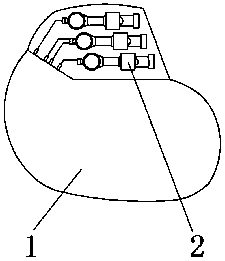
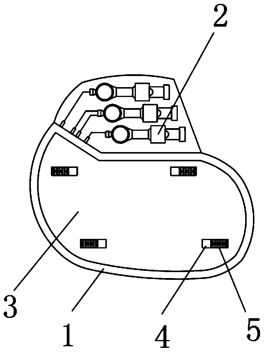
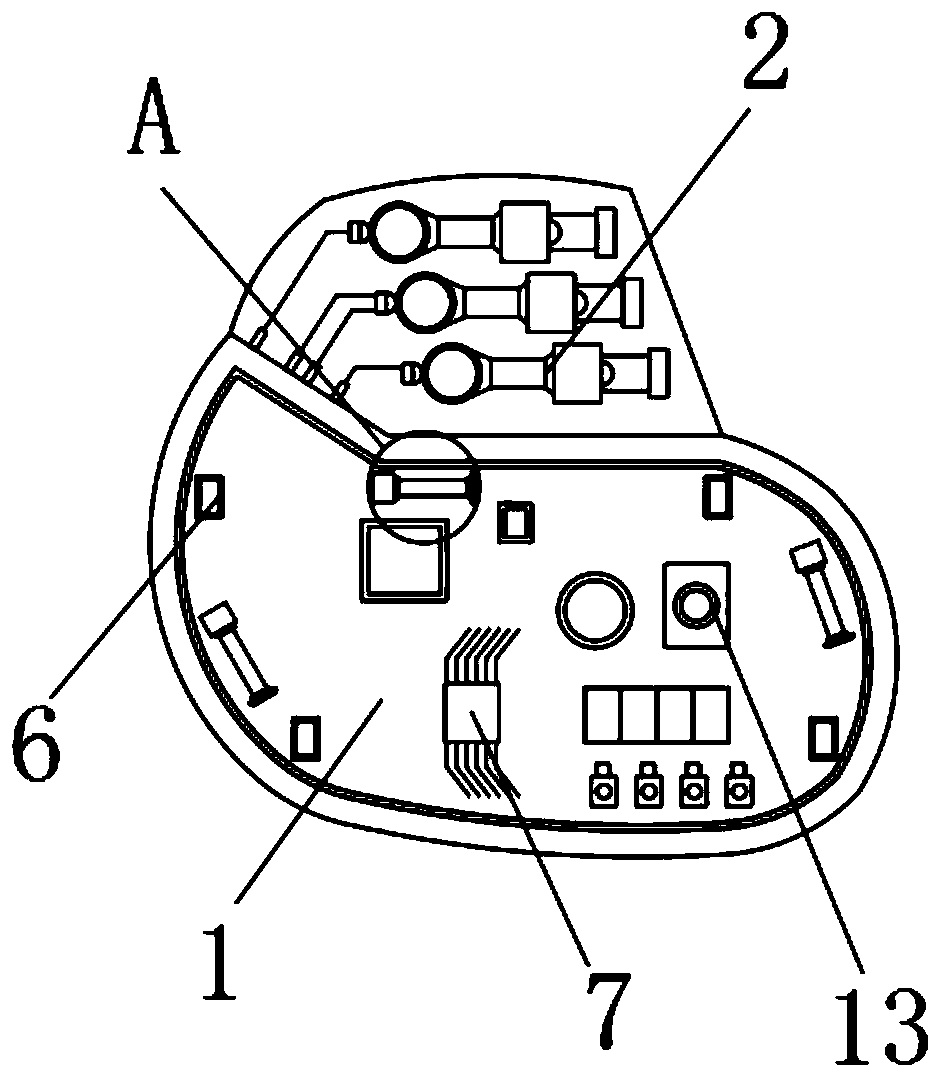
[0031] see Figure 1 to Figure 8 , the present invention provides a technical solution: a wireless charging cardiac pacemaker, comprising a housing 1, a connection block 2 located on the top of the housing 1, one side of the housing 1 is detachably connected to a connection bottom case 3, and the connection bottom case 3 There is an adjustment groove 4 on the surface of the surface, the adjustment slider 5 is slidably connected in the adjustment groove 4, the adjustment slider 5 can slide in the adjustment groove 4, the bottom of the connecting bottom case 3 is located at the bottom of the adjustment slider 5 and is fixedly connected with a connecting column 8. The bottom side of the connecting column 8 is fixedly connected with a positioning block 10. When the slider 5 is slid and adjusted, the sliding of the adjusting slider 5 can drive the connecting column 8 and the positioning block 10 to slide together. A positioning seat 6, a plurality of positioning seats 6 are provide...

Embodiment 2

[0041] see Figure 1 to Figure 8, the present invention provides a technical solution: a wireless charging cardiac pacemaker, comprising a housing 1, a connection block 2 located on the top of the housing 1, one side of the housing 1 is detachably connected to a connection bottom case 3, and the connection bottom case 3 There is an adjustment groove 4 on the surface of the surface, the adjustment slider 5 is slidably connected in the adjustment groove 4, the adjustment slider 5 can slide in the adjustment groove 4, the bottom of the connecting bottom case 3 is located at the bottom of the adjustment slider 5 and is fixedly connected with a connecting column 8. The bottom side of the connecting column 8 is fixedly connected with a positioning block 10. When the slider 5 is slid and adjusted, the sliding of the adjusting slider 5 can drive the connecting column 8 and the positioning block 10 to slide together. A positioning seat 6, a plurality of positioning seats 6 are provided...


PUM


Abstract

A wirelessly charged cardiac pacemaker comprises an outer shell and a connecting block located at the top of the outer shell, a connecting bottom shell is detachably connected to one side of the outershell, an adjusting groove is formed in the surface of the connecting bottom shell, and an adjusting sliding block is slidably connected into the adjusting groove; a connecting column is fixedly connected to the position, located at the bottom of the adjusting sliding block, of the bottom of the connecting bottom shell, a positioning block is fixedly connected to one side of the bottom of the connecting column, a plurality of positioning bases are fixedly connected to the interior of the outer shell, and connecting holes matched with the positioning block for use are formed in the positioningbases; according to the pacemaker, the practicability of the pacemaker is greatly improved through the arrangement of the multiple adjusting sliding blocks and the positioning base, the connecting bottom shell is effectively mounted and dismounted through the cooperative use of the adjusting sliding blocks and the positioning base, only the connecting bottom shell needs to be align with one sideof the shell, and then the connecting bottom shell can be mounted and fixed through the adjusting sliding blocks and the positioning base, operation is simple. Meanwhile, the use of special tools is reduced.

Description

technical field [0001] The invention belongs to the technical field of pacemakers, and in particular relates to a wireless charging pacemaker. Background technique [0002] Cardiac pacemaker is a product that assists the beating of the heart and has a therapeutic effect. It has helped thousands of people recover and saved many lives. With the development of science and technology, inside the pacemaker Equipped with a receiver, through the COTA internal transmitter, the COTA system can wirelessly charge the pacemaker and charge the space. At the same time, the radiation received is equivalent to that generated by the router, which can help more people recover and treatment. [0003] Existing pacemakers often require special tools for detection and disassembly, and it is often difficult to find special tools during detection. At the same time, due to the small size of pacemaker removal bolts, it is difficult to disassemble and easy to lose. Pacemakers often require It is use...

Claims


Application Information

Patent Timeline
Patent Type & Authority Applications(China)
IPC IPC(8): A61N1/362A61N1/375A61N1/378
CPCA61N1/362A61N1/37512A61N1/3756A61N1/378
Inventor 金虎林
Owner 上海佰恩智电子科技有限公司
Features
  • R&D
  • Intellectual Property
  • Life Sciences
  • Materials
  • Tech Scout
  • Unparalleled Data Quality
  • Higher Quality Content
  • 60% Fewer Hallucinations
Learn More