Multi-item combined industrial dust removal equipment

A dust-removing equipment and a combined technology, applied in combined devices, dispersed particle separation, chemical instruments and methods, etc., can solve the problems of inability to achieve dust-removing effect, dust shaking, and dust-collecting air bag blockage, etc. Ensure smooth flow and ensure the effect of cleanliness

Inactive Publication Date: 2020-07-28
叶霏
View PDF1 Cites 6 Cited by
  • Summary
  • Abstract
  • Description
  • Claims
  • Application Information

AI Technical Summary

Problems solved by technology

[0003] The patent application publication No. CN110302604 A discloses a combined dust removal device, which includes a main body, an air intake assembly is installed at one end of the main body, and an installation bin is installed at the other end of the main body, and a blower is installed at one end of the main body A. The inside of the main body is uniformly installed with a mounting plate, and the mounting plate is uniformly provided with threaded holes, and the inner side of the threaded holes is provided with a suitable mounting tube through a threaded groove. One end of the outer wall of the mounting tube A clamping strip is provided, a connecting ring suitable for it is provided on the outside of the installation pipe, and a clamping groove is provided on the inside of the connecting ring, the clamping groove and the clamping strip are suitable, and one end of the connecting ring is installed There is a ventilated side wall, and the inner side of the connecting ring is equipped with a dust collection air bag, the inner side of the installation warehouse is installed with a blower B, and one end of the main body is installed with a control panel, and the control panel is connected through a wire and a stepping motor. , blower A, and blower B are electrically connected; although this device can achieve the dust removal effect, the dust collection air bag cannot shake off the dust on the surface immediately during the dust removal process, which will easily cause the dust to block the dust collection air bag, which cannot be achieved. Efficient dust removal effect, for this reason, a multi-combined industrial dust removal equipment is now provided to solve the above technical problems

Method used


Image

  • Multi-item combined industrial dust removal equipment
  • Multi-item combined industrial dust removal equipment
  • Multi-item combined industrial dust removal equipment

Examples


Embodiment 1

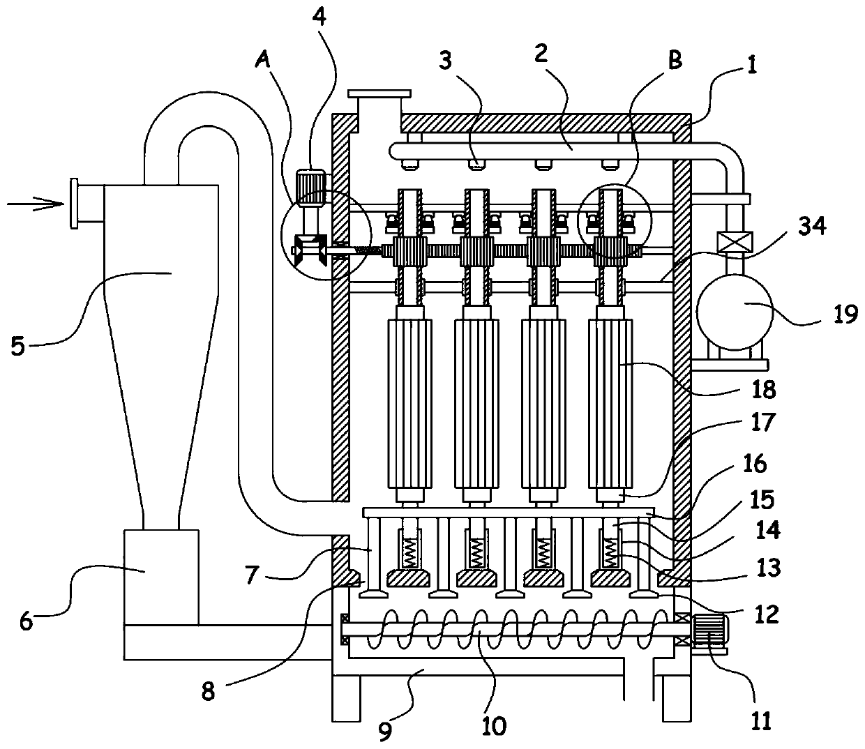
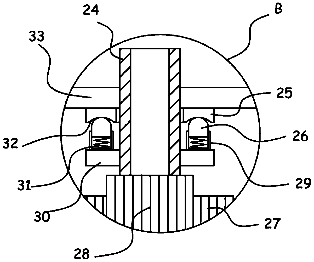
[0023] see Figure 1-4 , a multi-combined industrial dust removal equipment, including a dust removal box 1 and a cyclone separator 5, the bottom of the dust removal box 1 is equipped with a collection box 9 communicated through a blanking hole 8, and the top of the cyclone separator 5 extends to the In the dust removal box 1, an ash hopper 6 is installed at the bottom of the cyclone separator 5, and a sealing partition 34 is installed horizontally and fixedly in the dust removal box 1, and the sealing partition 34 is vertically slidably installed with several dust removal mechanisms distributed at equal intervals. The bottom of the dust removal box 1 is provided with a support guide assembly for supporting the dust removal mechanism. A horizontal plate 33 is horizontally fixed in the dust removal box 1. The dust removal mechanism includes an exhaust pipe 24 that vertically slides through the horizontal plate 33. The top of the exhaust pipe 24 is A purging mechanism is provide...

Embodiment 2

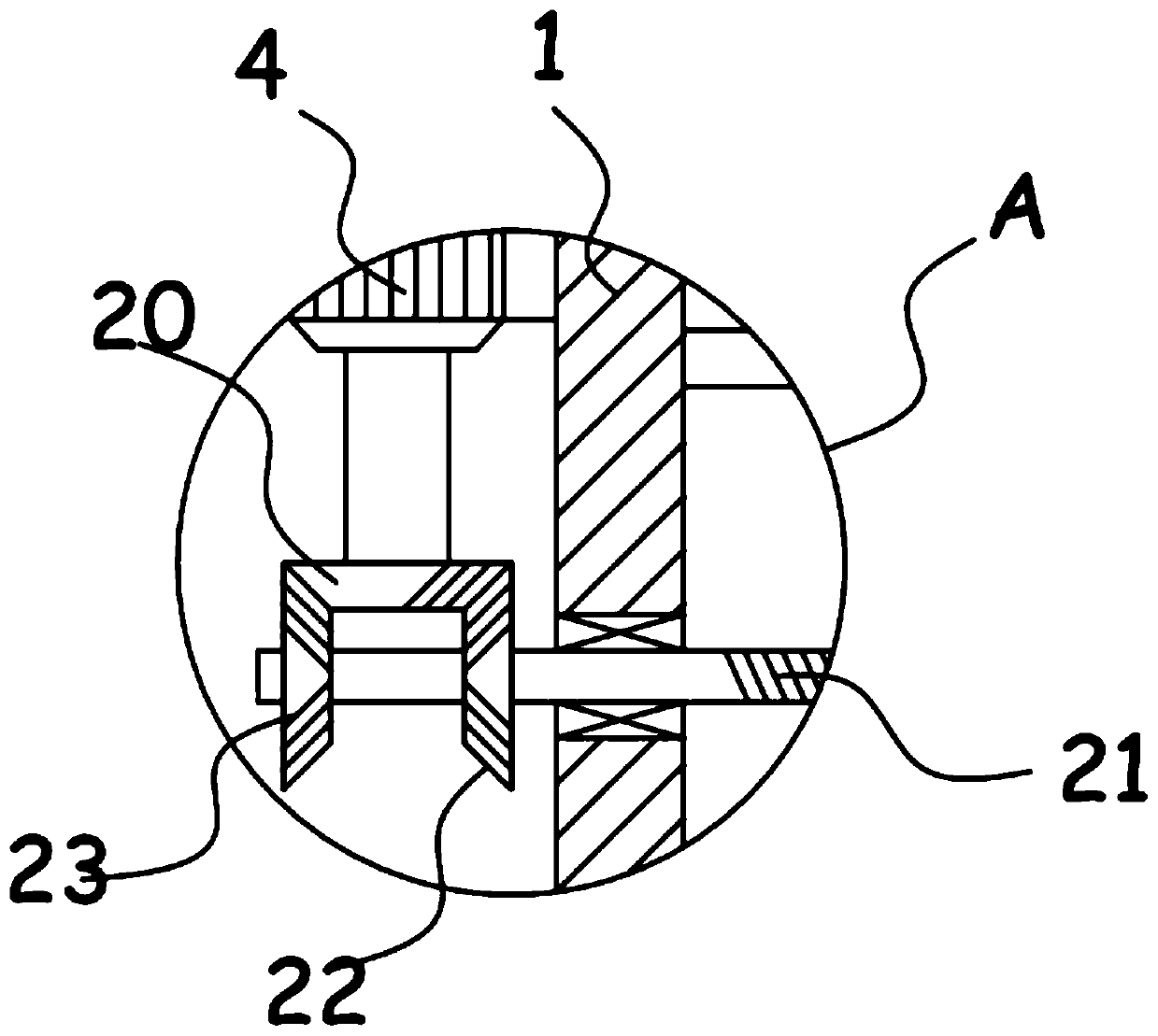
[0030] On the basis of Embodiment 1, in addition, the rotating mechanism of the device includes a rack 27 slidingly installed in the dust removal box 1, and the rack 27 is meshed with a gear 28 sleeved and fixed on the exhaust pipe 24. The screw rod 21 extending to the outside of the dust removal box 1 is installed on the internal thread connection of the rack 27. The screw rod 21 is sleeved with a bevel gear I22 and a bevel gear II23, and the bevel gear I22 and the bevel gear II23 are alternately meshed and connected to be driven by the motor I4. The incomplete bevel gear 20.

[0031] The motor I4 can drive the incomplete bevel gear 20 to rotate, and the incomplete bevel gear 20 can be meshed and connected with the bevel gear I22 and the bevel gear II23 alternately. At this time, the screw rod 21 realizes forward and reverse alternately, that is, the screw rod 21 drives the rack 27 to reciprocate horizontally. Sliding, the gear rack 27 drives the gear 28 to alternately rotate...


PUM


Abstract

The invention discloses multi-item combined type industrial dust removal equipment and relates to the technical field of industrial dust removal. The multi-item combined type industrial dust removal equipment comprises a dust removal box and a cyclone separator, a collecting box communicated through a discharging hole is installed at the bottom of the dust removal box, a supporting guide assemblyused for supporting a dust removal mechanism is arranged at the bottom of the dust removal box, a horizontal plate is horizontally fixed in the dust removal box, the dust removal mechanism comprises an exhaust pipe vertically and slidably penetrating through a horizontal plate, and a purging mechanism is arranged at the top of the exhaust pipe. According to the invention, a pleated cloth bag in the dust removal mechanism is used for blocking dust in air flow, the arranged blowing mechanism can blow air flow from the interior of the pleated cloth bag to the exterior of the pleated cloth bag, the effect of purging and removing dust on the outer surface of the pleated cloth bag is achieved, the pleated cloth bag can be expanded in the period, falling of dust is accelerated, the rotating mechanism can drive the pleated cloth bag to rotate in a reciprocating mode, the dust on the pleated cloth bag is thrown off from the pleated cloth bag, the cleanliness of the surface of the pleated clothbag can be well guaranteed, and the dust removal effect is greatly improved.

Description

technical field [0001] The invention relates to the technical field of industrial dust removal, in particular to a multi-component combined industrial dust removal equipment. Background technique [0002] Dust removal equipment refers to equipment that separates dust from flue gas, also called dust collector or dust removal equipment. The dust removal equipment uses the dust removal water pipe and compressed air pipeline in the well, adds certain additives to the water, introduces wind pressure, and completes a series of technological processes through special equipment to generate foam, which is sprayed to the dust source through the distributor and nozzle bracket assembly. , A large amount of dust is also produced in the process of industrial production, and dust removal equipment is required to achieve dust removal and purification effects. [0003] The patent application publication No. CN110302604 A discloses a combined dust removal device, which includes a main body, ...

Claims


Application Information

Patent Timeline
Patent Type & Authority Applications(China)
IPC IPC(8): B01D50/00B01D46/02B01D46/04
CPCB01D50/20
Inventor 叶霏
Owner 叶霏
Why Eureka
Try Eureka