Multi-channel liquid path system

A liquid system and multi-channel technology, applied in the field of material preparation, can solve the problems of inability to meet large-scale and efficient screening of catalysts, time-consuming and labor-intensive materials, lack of reliable solutions, etc., achieve good promotion and application prospects, flexible operation, and reduce experiments effect of error

Pending Publication Date: 2020-07-28
SUZHOU INST OF BIOMEDICAL ENG & TECH CHINESE ACADEMY OF SCI
View PDF0 Cites 1 Cited by
  • Summary
  • Abstract
  • Description
  • Claims
  • Application Information

AI Technical Summary

Problems solved by technology

However, in many laboratories and scientific research units, the distribution of these liquids is completely done manually, which is not only time-consuming, laborious and material-consuming, but also a single experiment lacks contrast, and the results are often affected by human errors.
In addition, the manual operation method can no longer meet the requirements of large-scale and efficient catalyst screening, and it has become an inevitable trend to automate part of the repeated experimental operation process, especially the liquid distribution process.
Therefore, realizing multi-channel liquid distribution through automatic control is a technical method to improve experimental efficiency and reduce experimental errors, but there is currently a lack of reliable solutions

Method used


Image

  • Multi-channel liquid path system
  • Multi-channel liquid path system
  • Multi-channel liquid path system

Examples


Embodiment 1

[0047] refer to Figure 5-11 , in this embodiment, a plurality of mounting holes 91 for accommodating the reaction kettle 9 are provided on the mounting seat 90, and a base 92 is detachably provided on the mounting base 92, and a dispensing needle mounting block 93 is detachably provided on the base 92;

[0048] The base 92 is provided with a groove 920, and the dispensing needle mounting block 93 is fitted in the groove 920. The corner of the groove 920 on the base 92 is rotatably connected with a plectrum 921, and the distributing needle mounting block 93 is inserted into the groove. Rotate the plectrum 921 after the inside of 920, so that the plectrum 921 is pressed on the top of the dispensing needle mounting block 93, thereby fixing the dispensing needle mounting block 93 on the base 92.

[0049] The dispensing needle mounting block 93 is provided with a needle hole 94 for inserting the first reagent needle 8 and / or the second reagent needle and communicating with the rea...

Embodiment 2

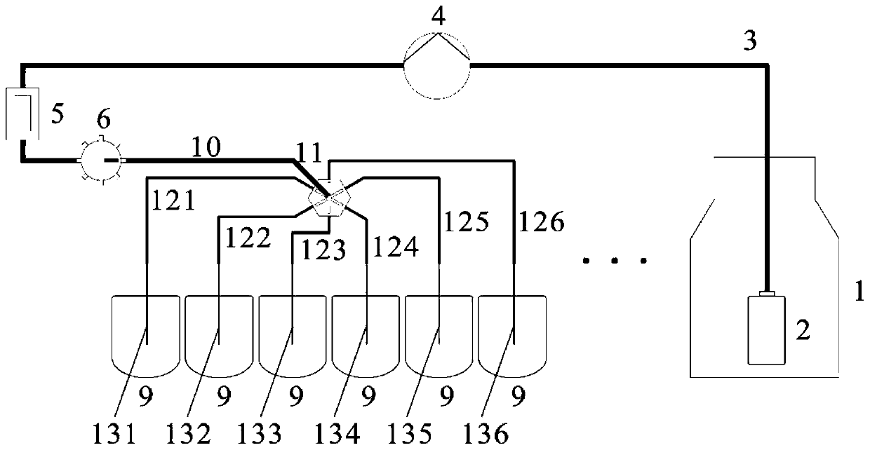
[0057] For example, in one embodiment, 12 different co-precipitation reactions need to be performed, and each co-precipitation reaction needs to add two different reaction liquids in the reaction kettle 9 . The functional requirements of the liquid circuit system are: after adding reagent 1, slowly add reagent 2 dropwise to ensure that the two reaction solutions fully react, and the proportions of reagent 1 and reagent 2 are different.

[0058] Corresponding to the liquid path distribution requirements, in this embodiment, a total of 7 precursor liquid path units, 12 single-channel reagent needle liquid path units, 2 multi-channel reagent needle liquid path units, and 12 reaction kettles 9 are included;

[0059] Among them, the reagent 1 is stored in the reaction liquid reservoir 1 of the six precursor liquid circuit units, and the reagent 2 is stored in the reaction liquid reservoir 1 of the other unit;

[0060] Among them, the channel 1 and channel 2 of the multi-channel swi...


PUM


Abstract

The invention discloses a multi-channel liquid path system. The system comprises at least one precursor liquid path unit for providing liquid, at least one single-channel reagent needle liquid path unit communicating with the output end of the precursor liquid path unit, and at least one multi-channel reagent needle liquid path unit communicating with the output end of the precursor liquid path unit and capable of carrying out multi-channel isopyknic distribution on liquid provided by the precursor liquid path unit. According to the invention, independent distribution of liquid in a single reaction kettle can be realized through the single-channel reagent needle liquid path unit, isopyknic feeding of a plurality of reaction kettles can be realized through the multi-channel reagent needle liquid path unit, and automatic feeding of various reagents in a single reaction kettle can be realized through combined use of the single-channel reagent needle liquid path unit and the multi-channelreagent needle liquid path unit; and automatic distribution of various reagents can be realized, and compared with a manual operation method, the multi-channel liquid path system has the advantages that liquid distribution efficiency is greatly improved, experimental errors are reduced, operation is flexible and popularization and application prospects are good.

Description

technical field [0001] The invention relates to the technical field of material preparation, in particular to a multi-channel liquid circuit system. Background technique [0002] In the fields of petrochemical, energy, and biomedicine, liquid distribution is a widely existing step in the experimental process, especially when some experiments such as wet chemical methods are used to prepare materials (such as catalysts), researchers need to carry out a large amount of liquid distribution to prepare and select Material. However, in many laboratories and scientific research units, the distribution of these liquids is completely done manually, which is not only time-consuming, laborious and material-consuming, but also a single experiment lacks contrast, and the results are often affected by human errors. In addition, the manual operation method can no longer meet the requirements of large-scale and efficient catalyst screening, and it has become an inevitable trend to automate...

Claims


Application Information

Patent Timeline
Patent Type & Authority Applications(China)
IPC IPC(8): B01L3/02
CPCB01L3/0293
Inventor 葛阳曹炜吴炎凡刘祎牛群王学军
Owner SUZHOU INST OF BIOMEDICAL ENG & TECH CHINESE ACADEMY OF SCI
Why Eureka
Try Eureka