
A new energy vehicle motor drive control and vehicle speed safety protection method

A technology of motor drive control and new energy vehicles, which is applied in the direction of control drives, control devices, vehicle components, etc., can solve the problems of high indirect cost pressure, expensive cost consumption, hidden safety hazards, etc., to ensure safe parking, realize low cost, The effect of high reliability

Active Publication Date: 2022-05-31
HIGER
View PDF4 Cites 0 Cited by
  • Summary
  • Abstract
  • Description
  • Claims
  • Application Information

AI Technical Summary

Problems solved by technology

When the motor speed acquisition equipment fails, the electronic rotor information is abnormal, which affects the torque control of the motor controller to the motor, and further affects the safety of the vehicle when driving and fault parking; at the same time, it also makes the speed information abnormal, which further leads to vehicle speed information. Abnormal, if the vehicle is in the operation mode of speed control at this time, such as: maximum speed limit, constant speed creep control, constant speed cruise, etc., the abnormal speed feedback directly affects the control of the whole vehicle, and even causes the vehicle to lose control, triggering "speeding "And other accidents, bringing safety hazards
[0003] Adding acquisition equipment or replacing high-precision acquisition equipment will bring expensive cost consumption, as well as complex vehicle repair and maintenance problems; for the existing installation space and electrical interface on the vehicles currently in the market, adding equipment is necessary for equipment mechanical installation, There are big implementation problems in the electrical connection, in addition to the docking of data information with the whole vehicle, which may require multiple equipment hardware changes, software debugging and modification, the implementation of the restructuring is difficult, and the implementation period of the restructuring is long, which leads to the outage of the vehicle The indirect cost pressure of the

Method used


Image

  • A new energy vehicle motor drive control and vehicle speed safety protection method
  • A new energy vehicle motor drive control and vehicle speed safety protection method
  • A new energy vehicle motor drive control and vehicle speed safety protection method

Examples


Embodiment

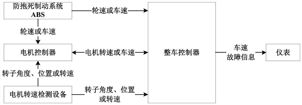
[0048] Step 11, the motor rotational speed detection equipment detects the rotational speed of the motor, and sends the motor rotational speed information to the motor controller.

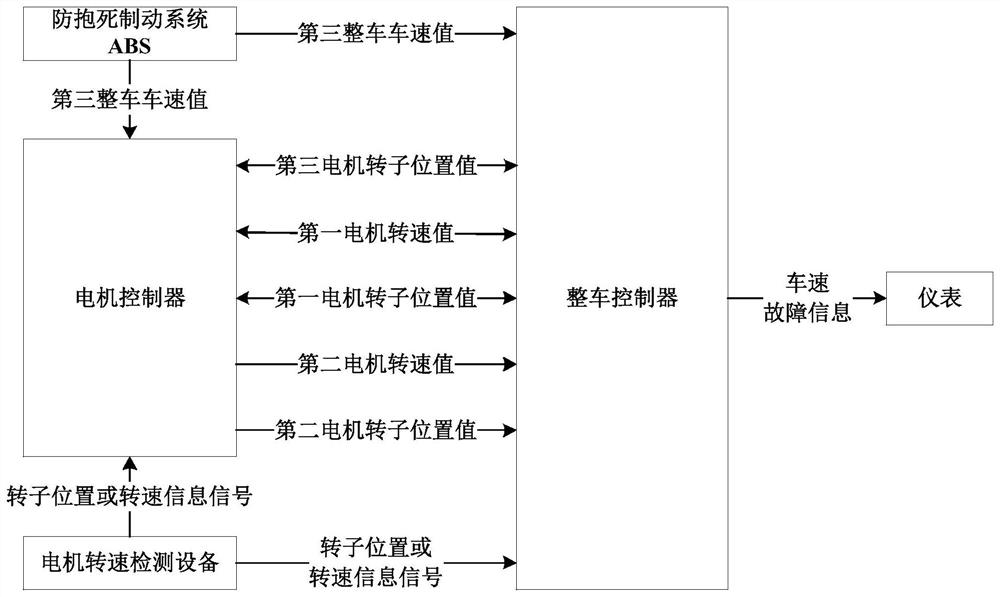
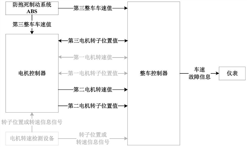
[0067] Step 3, the vehicle controller starts the corresponding vehicle protection strategy according to the situation of the rotational speed value credible factor.

[0069] The vehicle controller is at the minimum confidence factor of the rotor position value of the first motor or the possibility of the rotor position value of the second motor.

[0070] The vehicle controller starts the vehicle protection of the vehicle when the confidence factor of the rotor position value of the third motor is the smallest.

[0080] The above-mentioned serial numbers of the embodiments of the present application are only for description, and do not represent the pros and cons of the embodiments.


PUM


Abstract

The invention discloses a new energy vehicle motor drive control and vehicle speed safety protection method, which is applied to a new energy vehicle including a vehicle controller, a motor controller, a motor speed detection device, and an anti-lock braking system ABS, including: calculating Three sets of motor speed values, motor rotor position values, and vehicle speed values ​​are generated, and corresponding credibility factors are established for the three sets of motor rotor position values; the credibility factors of each position value are adjusted according to the vehicle's own state, and the maximum credibility factor is used to correspond to The motor speed value and the motor rotor position value; the vehicle controller starts the corresponding vehicle protection strategy according to the reliability factor of the speed value. No need to add equipment to modify the original car, low cost, fast response, high reliability.

Description

A new energy vehicle motor drive control and vehicle speed safety protection method technical field The invention belongs to the field of motor drive systems, and relates to a kind of new energy vehicle motor drive control and vehicle speed safety protection. protection method. Background technique [0002] As a kind of energy-saving and environment-friendly products, new energy vehicles have very good prospects for use. At present, new energy vehicles adopt The motor is used as a power drive device, and the motor rotor position and motor rotation are calculated solely through the motor speed acquisition device. The speed of the motor is calculated in combination with the reduction ratio of the rear axle of the vehicle and the rolling radius of the tire to obtain the corresponding vehicle speed value. When the motor When the speed acquisition device fails, the electronic rotor information is abnormal, which affects the torque control of the motor by the motor control...

Claims


Application Information

Patent Timeline
Patent Type & Authority Patents(China)
IPC IPC(8): B60L15/20B60K35/00B60W50/02
CPCB60L15/20B60K35/00B60W50/0205B60L2240/421B60L2240/12Y02T10/72
Inventor 史成龙熊金峰程方斌彭程朱乐凯
Owner HIGER
Learn More