Device pressing device of optical fiber fixing element

A technology of fixing components and pressing devices, applied in the direction of optical fiber/cable installation, etc., can solve problems such as optical fiber slipping and affecting cutting accuracy, and achieve the effects of firm fixing, prolonging service life, and reducing pressure

Inactive Publication Date: 2020-07-28
南京双电科技实业有限公司
View PDF6 Cites 0 Cited by
  • Summary
  • Abstract
  • Description
  • Claims
  • Application Information

AI Technical Summary

Problems solved by technology

[0004] The purpose of the present invention is to provide a device clamping device for optical fiber fixing components to solve the problem that the existing optical fiber proposed in the background technology is usually manually fixed, that is, manually clamped and fixed, and manual clamping is prone to optical fiber slippage, thereby Problems Affecting Shearing Accuracy

Method used


Image

  • Device pressing device of optical fiber fixing element
  • Device pressing device of optical fiber fixing element
  • Device pressing device of optical fiber fixing element

Examples


Embodiment Construction

[0029] The following will clearly and completely describe the technical solutions in the embodiments of the present invention with reference to the accompanying drawings in the embodiments of the present invention. Obviously, the described embodiments are only some, not all, embodiments of the present invention.

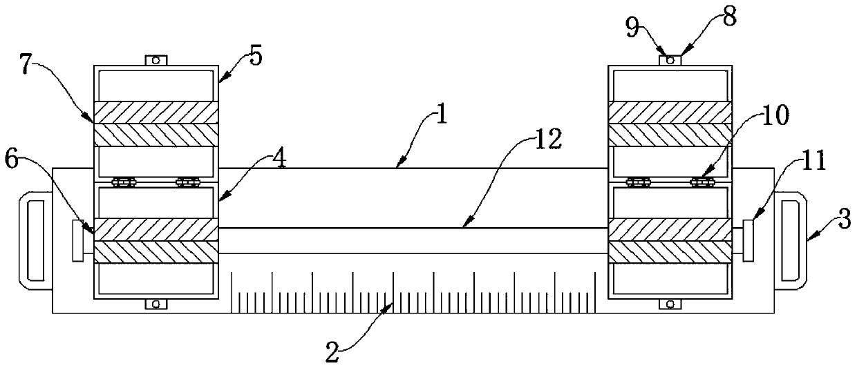
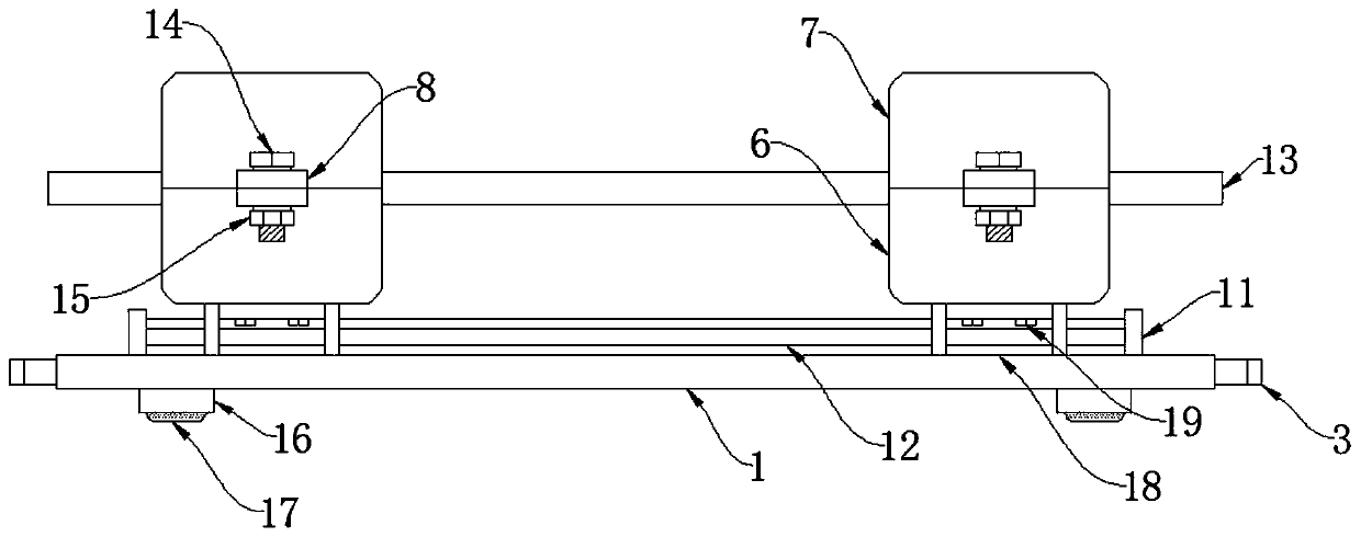
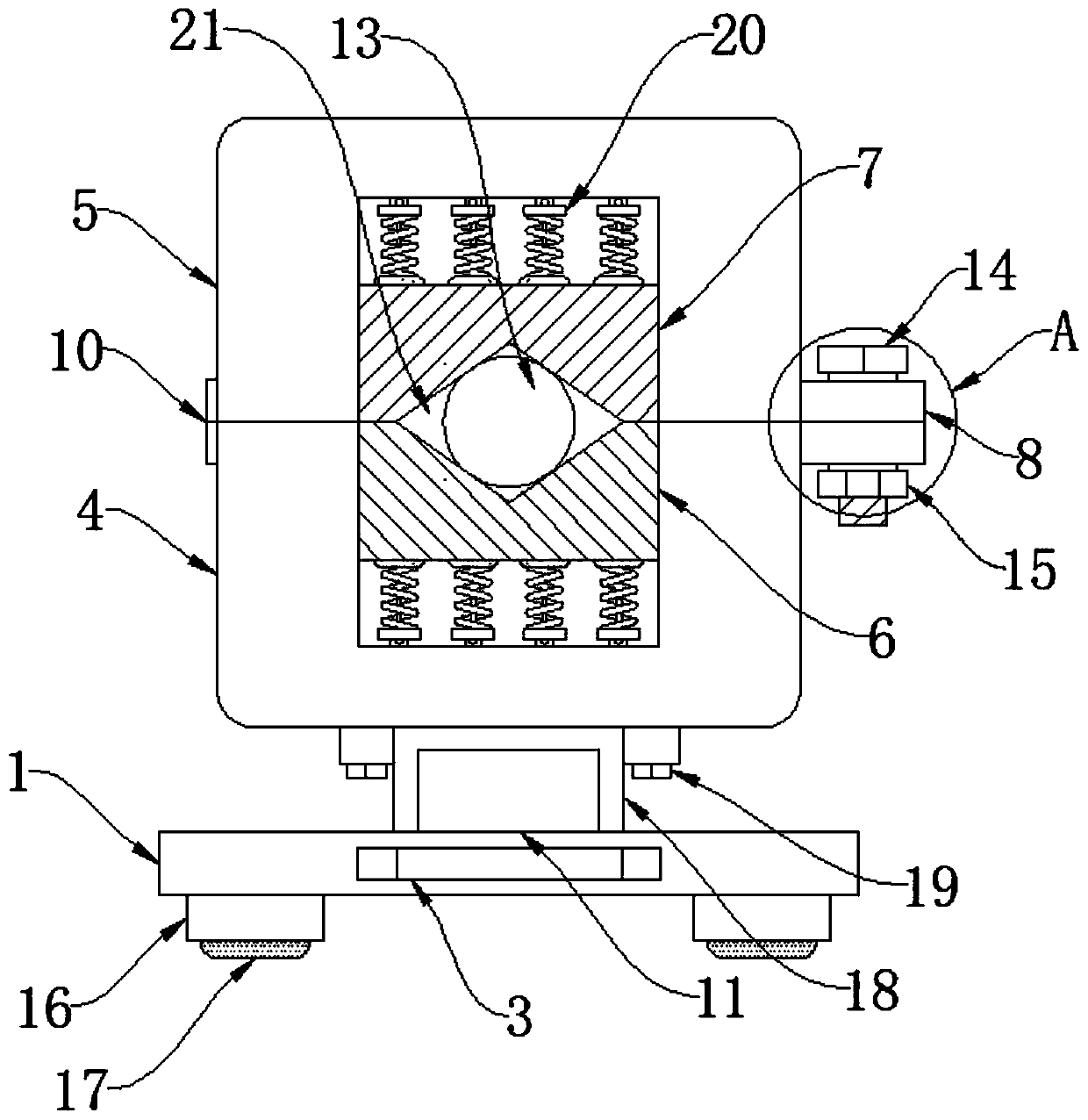
[0030] see Figure 1-6 , an embodiment provided by the present invention: a device pressing device for fixing optical fiber components, including a workbench 1, a foot 16 is installed under the workbench 1, and a shock-absorbing anti-skid pad 17 is provided on the lower surface of the foot 16 , the shock-absorbing anti-slip pad 17 can make the contact between the workbench 1 and the desktop more dense, thereby increasing the friction between the workbench 1 and the tabletop, and playing the role of shock absorption and anti-slip. Both sides of the workbench 1 are equipped with pull handles 3. The pull handle 3 can easily move the entire pressing device. The upper sur...


PUM


Abstract

The invention discloses a device pressing device of an optical fiber fixing element and relates to the technical field of pressing devices. According to the prior art, an existing optical fiber is generally fixed manually, namely, the optical fiber is pressed and fixed manually, and as a result, the optical fiber is prone to slipping off during manual pressing, and shearing precision is affected.The invention just aims to solve the above problems in the prior art. Footstands are installed below a workbench; shock absorption non-slip mats are arranged on the lower surfaces of the footstands; pull handles are installed on the two sides of the workbench correspondingly; scale marks are arranged on the upper surface of the workbench; a sliding rail is installed on the workbench; the sliding rail is connected with the workbench in a welded mode; limiting blocks are installed at the two ends of the sliding rail; a sliding block is arranged on the sliding rail; the sliding block is connectedwith the sliding rail in a sliding mode; metal scrapers are installed on the two sides of the sliding block; a sliding block installation plate is arranged above the sliding block; and four screw holes are formed in the sliding block installation plate.

Description

technical field [0001] The invention relates to the technical field of pressing devices, in particular to a device pressing device for fixing components of optical fibers. Background technique [0002] Optical fiber devices are also called optical passive devices. Because the propagation speed of light in different substances is different, when light is shot from one substance to another, refraction and reflection will occur at the interface of the two substances. When the angle of the incident light reaches or exceeds a certain angle, the refracted light will disappear, and all the incident light will be reflected back. This is the total reflection of light. Different substances have different refraction angles for light of the same wavelength. The refraction angles of different wavelengths of light are also different, and optical fiber communication is formed based on the above principles. In daily life, because the transmission loss of light in optical fibers is much low...

Claims


Application Information

Patent Timeline
IPC IPC(8): G02B6/46
CPCG02B6/46
Inventor 卢俊
Owner 南京双电科技实业有限公司
Why Eureka
Try Eureka