Reflective transparent display device and application thereof

A transparent display and reflective technology, applied in optics, instruments, optical components, etc., can solve the problems of poor light efficiency and high power consumption of HUD head-up display devices, and achieve the effect of clear observation of display information and clear observation

Pending Publication Date: 2020-07-28
FUTURUS TECH CO LTD
View PDF3 Cites 3 Cited by
  • Summary
  • Abstract
  • Description
  • Claims
  • Application Information

AI Technical Summary

Problems solved by technology

[0007] Purpose of the invention: In order to overcome the problems of poor light efficiency and high power consumption of HUD head-up display devices in the prior art, the present invention provides a reflective transparent display device with high light efficiency and low power consumption

Method used


Image

  • Reflective transparent display device and application thereof
  • Reflective transparent display device and application thereof
  • Reflective transparent display device and application thereof

Examples


Embodiment 1

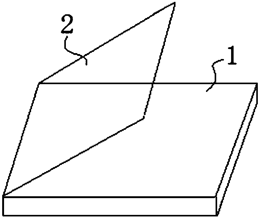
[0038] A reflective transparent display device of this embodiment, refer to figure 1 , including a host body 1 and a reflective cover 2, the light emitted from the host body 1 reaches the reflective cover 2 and is reflected to the human eye through the reflective cover 2, the host body 1 and the reflective cover 2 can be connected or separated, the host body 1. The reflective cover 2 can be fixedly connected or flexibly connected. The main body 1 and the reflective cover 2 can be flexibly connected through the electric shaft. 1 Rotate relative to the reflective cover 2, at this time, a certain angle is formed between the host body 1 and the reflective cover 2;

[0039] The host body 1 includes a housing and an image source device. The housing can be made of aluminum alloy or other materials. The image source device is used to emit light. The light emitted by the image source device reaches the reflective cover 2 and is reflected by the reflective cover 2. To the human eye, a ...

Embodiment 2

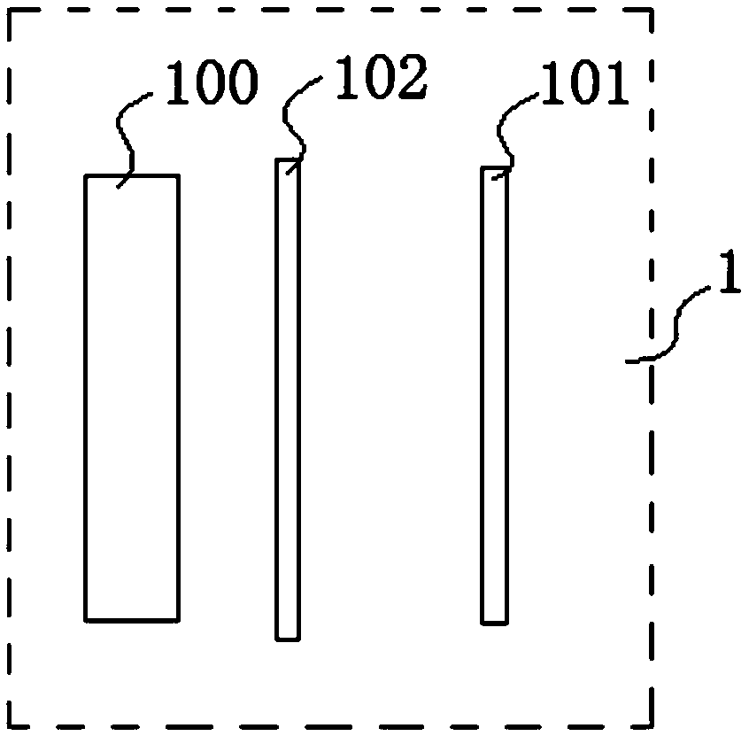
[0041] A reflective transparent display device of this embodiment is based on Embodiment 1, refer to figure 1 , figure 2 with image 3 , wherein the image source device includes a backlight system 100 and an LCD101, but not limited to this structure, the backlight system 100 is used to emit light from the light source, and after the light from the light source reaches the LCD101, the light from the image source emitted by the LCD101 reaches the reflective cover 2, and passes through the reflective cover 2 Reflected to the human eye to form a virtual image.

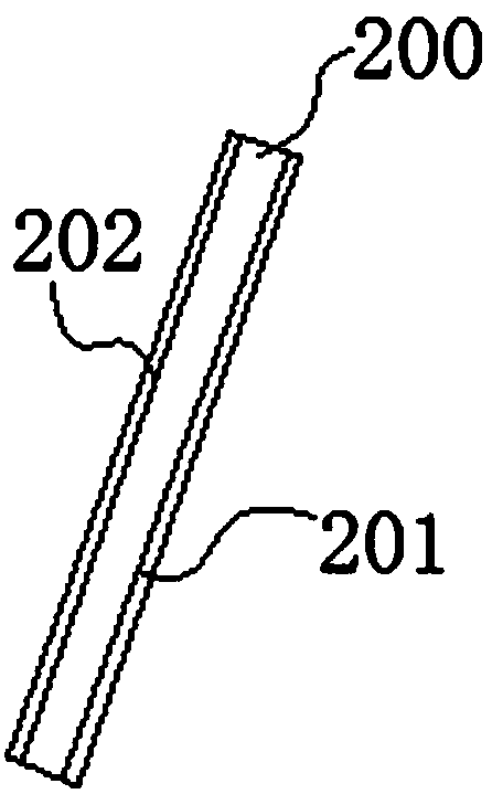
[0042] Wherein the reflective cover plate 2 includes a transparent substrate 200, which can be used to reflect the outgoing light from the image source device, and can also be used to transmit ambient light from the outside. After the transparent substrate 200 reflects the outgoing light from the image source device A virtual image is formed in front of the human eye, and the human eye can watch the external environment...

Embodiment 3

[0044] A reflective transparent display device of this embodiment is based on Embodiment 2, refer to figure 1 , figure 2 with image 3 , wherein the reflective cover plate 2 includes a polarized transflective film 201, which is arranged on the inner surface of the transparent substrate 200, and in a specific application, the polarized transflective film 201 is arranged on the inner surface of the transparent substrate 200, namely on the side facing the driver. At this time, the backlight system 100 emits polarized light, and the reflective cover plate 2 reflects the polarized light. For example, when the backlight system 100 emits S-polarized light, the polarized transflective film 201 disposed on the inner surface of the transparent substrate 200 reflects the S-polarized light. Thereby forming a virtual image in front of people's eyes; when the backlight system 100 emits P polarized light, the polarized transflective film 201 arranged on the inner surface of the transparen...


PUM

PropertyMeasurementUnit
reflectanceaaaaaaaaaa
translucencyaaaaaaaaaa
reflectanceaaaaaaaaaa

Abstract

The invention discloses a reflective transparent display device and belongs to the technical field of optical display. The device comprises a host machine body and a reflection cover plate; light emitted by the host machine body reaches the reflection cover plate and then is reflected to human eyes through the reflection cover plate; the host machine body comprises an image source device; the image source device is used for emitting light; the image source device is used for reflecting emergent light to the human eyes through the reflection cover plate after the emergent light reaches the reflection cover plate; the reflection cover plate comprises a transparent base material and a polarization transflective film arranged on the surface of the transparent base material. The device is highin lighting effect, low in power consumption and capable of enabling a driver to clearly observe virtual image display information without hindering viewing of an external environment.

Description

technical field [0001] The invention belongs to the technical field of optical display, and in particular relates to a reflective transparent display device and an application thereof. Background technique [0002] The HUD head-up display can help people not need to look down at the instrument panel, but can view all kinds of driving information they need through the head-up HUD head-up display, reducing the probability of looking down at the instrument panel, avoiding interruption of attention and loss of state awareness Because of the convenience of HUD and the ability to improve the safety of flight and driving, it has been applied in many industries. [0003] During the use of the HUD head-up display, it can display many types of information to the driver. The information is displayed through the image formed by the optical imaging system of the HUD head-up display, such as information on various instrument panels, speed, tire pressure, fuel consumption, etc. , People d...

Claims


Application Information

Patent Timeline
Patent Type & Authority Applications(China)
IPC IPC(8): G02B27/01G02B5/30
CPCG02B5/30G02B27/0101
Inventor 方涛徐俊峰吴慧军
Owner FUTURUS TECH CO LTD
Why Eureka
Try Eureka