
Semiconductor plasma machine

A plasma machine and semiconductor technology, which is applied in semiconductor/solid-state device manufacturing, circuits, discharge tubes, etc., can solve problems such as poor sealing effect, and achieve the effects of improving uniformity, solving poor sealing effect, and improving sealing effect.

Pending Publication Date: 2020-07-28
江苏壹度科技股份有限公司
View PDF0 Cites 0 Cited by
  • Summary
  • Abstract
  • Description
  • Claims
  • Application Information

AI Technical Summary

Problems solved by technology

[0004] The object of the present invention is to provide a semiconductor plasma machine to solve the problem of poor sealing effect of the semiconductor plasma machine proposed in the above-mentioned background technology

Method used


Image

  • Semiconductor plasma machine
  • Semiconductor plasma machine
  • Semiconductor plasma machine

Examples


Embodiment 1

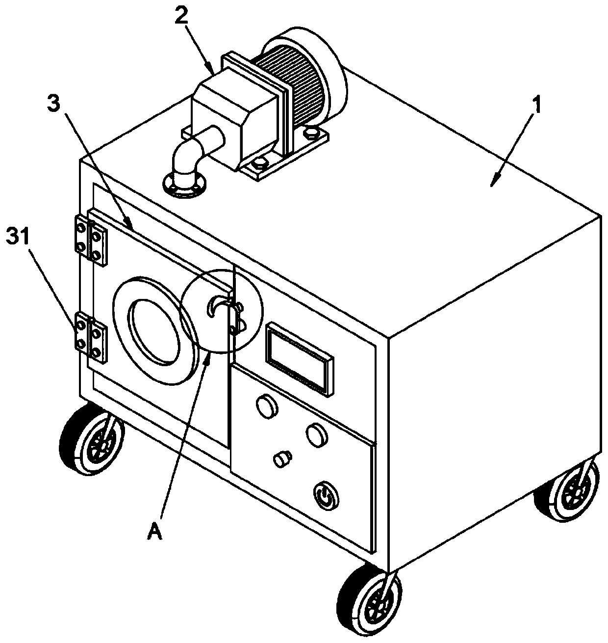
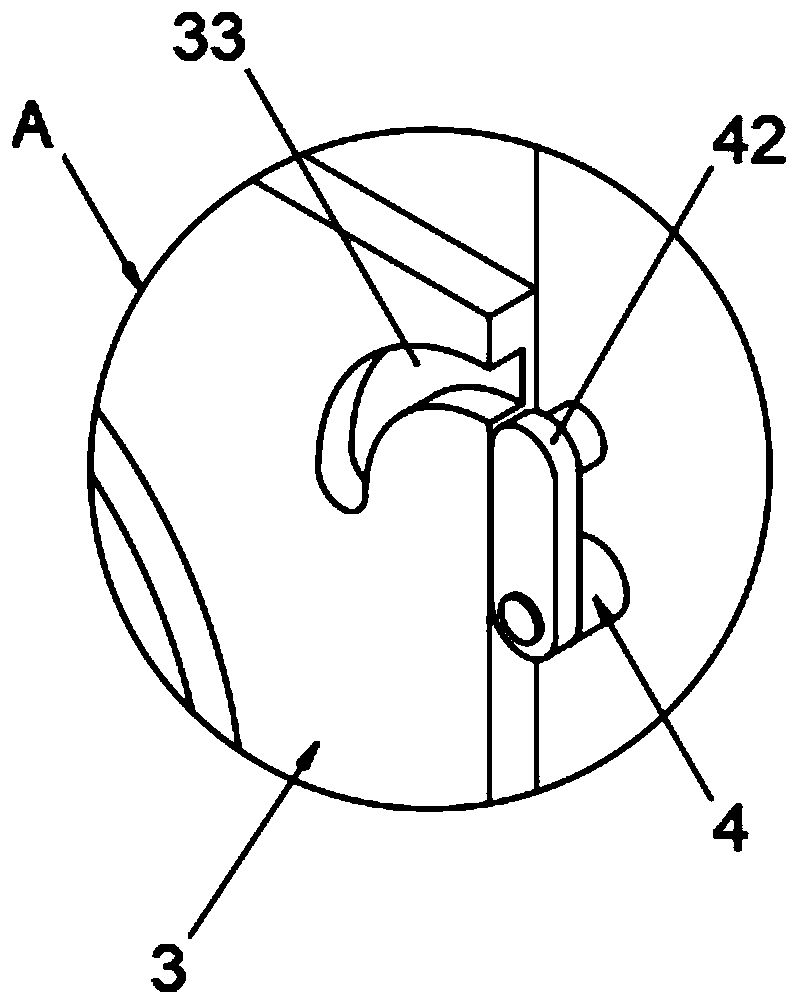
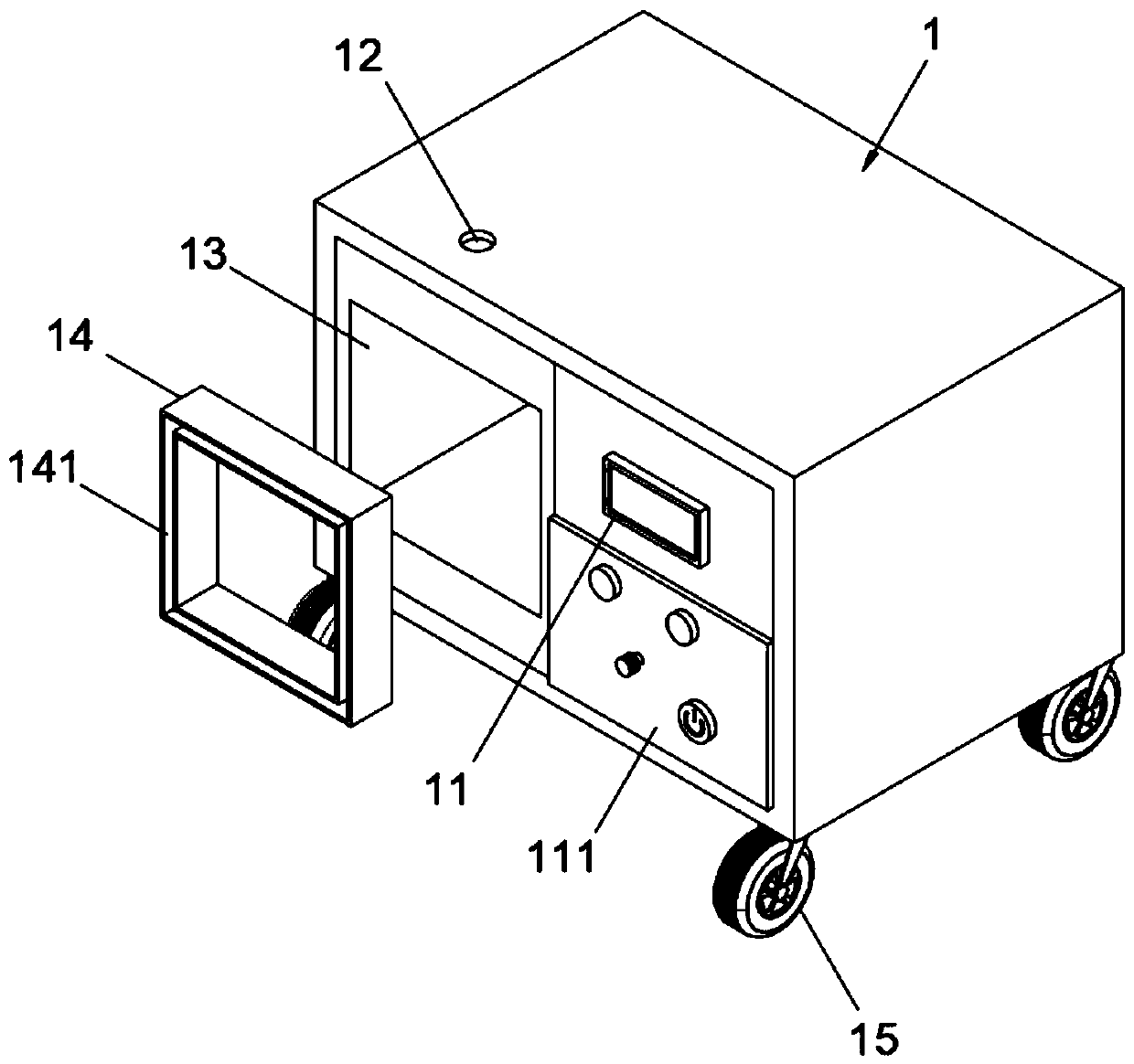
[0028] A semiconductor plasma machine, such as Figure 1-6 As shown, the plasma machine body 1 is included, the front surface of the plasma machine body 1 is provided with a display screen 11, the bottom of the display screen 11 is provided with a control panel 111, and the upper surface of the plasma machine body 1 is provided with a through hole 12. The front surface of the plasma machine body 1 is located on one side of the display screen 11 and is provided with an etching chamber 13. The through hole 12 communicates with the etching chamber 13. The upper surface of the plasma machine body 1 is provided with a vacuum pump 2, and both sides of the vacuum pump 2 are provided with a second vacuum pump. One bolt 21, the vacuum pump 2 is fixedly connected with the upper surface of the plasma machine body 1 through the first bolt 21, the output end of the vacuum pump 2 is provided with a suction pipe 22, and one end of the suction pipe 22 extends into the etching chamber 13 throug...

Embodiment 2

[0040] As the second preferred embodiment of the present invention, the four corners of the lower surface of the plasma machine body 1 are equipped with rollers 15 , which facilitates the movement of the plasma machine body 1 by the rollers 15 .

Embodiment 3

[0042] As a third preferred embodiment of the present invention, a gasket 232 is provided at the joint between the flange 23 and the through hole 12 , so that the gasket 232 can be used to improve the sealing effect between the exhaust pipe 22 and the through hole 12 .


PUM


Abstract

The invention relates to the technical field of plasma machines, and particularly relates to a semiconductor plasma machine. The semiconductor plasma machine comprises a plasma machine body, wherein the plasma machine body is provided with an etching bin, a vacuum pump is arranged on the upper surface of the plasma machine body, an exhaust pipe is arranged at the output end of the vacuum pump, a bin door is arranged on the etching bin, a hollow sealing gasket is arranged in the etching bin, a rectangular groove is formed in the front surface of the hollow sealing gasket, and a rectangular plugis arranged on the rear surface of the bin door. According to the semiconductor plasma machine, a stop block is rotated by using a rotating shaft after the bin door is closed, a limiting column is enabled to slide into the other end of the arc-shaped groove from one end of the arc-shaped groove, the bin door is buckled and pressed at the opening position of the etching bin by the limiting columnso as to close the bin door, the rectangular plug is matched with the hollow sealing gasket in an inserted mode through the rectangular groove at the same time, the sealing effect of the connecting position of the bin door and the etching bin is improved, oxidizing gas in air is prevented from entering the etching bin, the uniformity of semiconductor surface etching is improved, and the problem that the sealing effect of the semiconductor plasma machine is poor is solved.

Description

technical field [0001] The invention relates to the technical field of plasma machines, in particular to a semiconductor plasma machine. Background technique [0002] Semiconductor plasma machine is also called plasma etching machine. Plasma etching is the most common form of dry etching. Its principle is that the gas exposed to the electron area forms a plasma, and the resulting ionized gas and release of high-energy electrons Composed of gases, which form a plasma or ions, the ionized gas atoms, when accelerated by an electric field, release sufficient force with surface repelling forces to tightly bond materials or etch surfaces. [0003] At present, the semiconductor plasma machine needs to be etched in a vacuum environment, but the sealing effect of the existing plasma machine is poor, so that the oxidizing gas in the air enters the plasma machine, resulting in uneven etching of the semiconductor surface, which is not easy to use. In view of this, we propose a semicond...

Claims


Application Information

Patent Timeline
IPC IPC(8): H01J37/32H01L21/67
CPCH01J37/32513H01J2237/334H01L21/67069
Inventor 凌永康张勇何於
Owner 江苏壹度科技股份有限公司
Learn More