Polishing device for mechanical accessory processing

A technology for polishing devices and mechanical accessories, which is applied in the direction of grinding/polishing safety devices, grinding drive devices, metal processing equipment, etc. It can solve the problems of unable to polish the outer wall of the pipe, move the pipe, and incompletely polish the pipe, etc., to achieve Facilitate collection and sorting, reduce friction

Inactive Publication Date: 2020-07-31
JIAXING UNIV
View PDF7 Cites 3 Cited by
  • Summary
  • Abstract
  • Description
  • Claims
  • Application Information

AI Technical Summary

Problems solved by technology

[0002] Machining refers to the process of changing the shape, size or performance of the workpiece through a mechanical device. According to the difference in processing methods, it can be divided into cutting processing and pressure processing. When processing pipes, the outer wall of the pipe needs to be polished by a polishing machine. In the polishing and grinding operation, in order to avoid the shaking of the pipe, resulting in incomplete polishing of the pipe, the pipe will be clamped by a fixing mechanism, which makes it impossible for people to move the pipe during polishing, resulting in low polishing efficiency and the inability to clean the outer wall of the pipe. Comprehensive polishing treatment, the waste generated during polishing cannot be collected and processed in time

Method used


Image

  • Polishing device for mechanical accessory processing
  • Polishing device for mechanical accessory processing
  • Polishing device for mechanical accessory processing

Examples


Embodiment 1

[0028] Such as figure 1 shown;

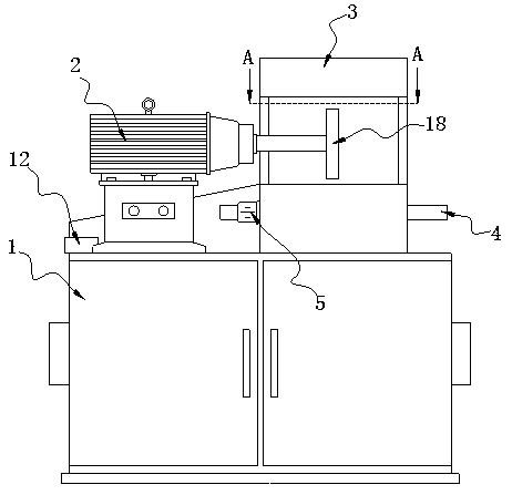
[0029] figure 1 It is a structural schematic diagram of the present invention.

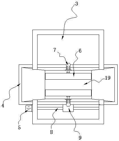
[0030] A polishing device for processing mechanical parts, comprising a cabinet 1, a driving motor 2 fastened with bolts on the cabinet 1, an output shaft of the driving motor 2 is rotatably connected to a polishing wheel 18, and a shell 3 is arranged outside the polishing wheel 18, and the shell 3 It is welded and fixed with the cabinet 1, and the side of the shell 3 away from the cabinet 1 is provided with a pull-in plate 4, which is slidingly connected with the shell 3, and the side of the shell 3 is fixed with a servo motor 5, and the servo motor 5 The output shaft runs through the housing 3 and is connected to a screw 8 in rotation. The end of the screw 8 away from the servo motor 5 is rotationally connected to the inner wall of the housing 3 . The two sides of the drawer plate 4 are symmetrically provided with a hydraulic cylinder 7, the hydraulic cylinder...


PUM


Abstract

The invention belongs to the technical field of machining, and in particular relates to a polishing device for mechanical accessory processing. The polishing device comprises a cabinet. A driving motor is fastened to the cabinet through a bolt, an output shaft of the driving motor is rotatably connected to a polishing wheel, a housing is arranged outside the polishing wheel, the housing is weldedand fixed to the cabinet, a thrusting plate is arranged on the side, far away from the cabinet, of the housing, the thrusting plate is slidably connected to the housing, a servo motor is fixedly arranged on one side of the housing, and an output shaft of the servo motor penetrates the housing. A tubular product is placed between clamping plates. When a hydraulic air cylinder works, the hydraulic air cylinder stretches to push the clamping plates to be close to each other till a rotary wheel is attached to the tubular product. When the servo motor works, an output shaft of the servo motor drives a screw to rotate, so that a sliding seat drives the thrusting plate to move synchronously through a screw, and therefore, it is convenient for people to move the tubular product in real time through the servo motor when polishing the tubular product.

Description

technical field [0001] The invention belongs to the technical field of mechanical processing, and in particular relates to a polishing device for processing mechanical parts. Background technique [0002] Machining refers to the process of changing the shape, size or performance of the workpiece through a mechanical device. According to the difference in processing methods, it can be divided into cutting processing and pressure processing. When processing pipes, the outer wall of the pipe needs to be polished by a polishing machine. In the polishing and grinding operation, in order to avoid the shaking of the pipe, resulting in incomplete polishing of the pipe, the pipe will be clamped by a fixing mechanism, which makes it impossible for people to move the pipe during polishing, resulting in low polishing efficiency and the inability to clean the outer wall of the pipe. Comprehensive polishing treatment, the waste generated during polishing cannot be collected and processed ...

Claims


Application Information

Patent Timeline
Patent Type & Authority Applications(China)
IPC IPC(8): B24B5/04B24B41/06B24B47/12B24B55/06B24B55/12
CPCB24B5/04B24B41/062B24B41/067B24B47/12B24B55/06B24B55/12
Inventor 朱荷蕾杨超黄风立陈如清陈军委
Owner JIAXING UNIV
Why Eureka
Try Eureka