Supercharge Your Innovation With Domain-Expert AI Agents!

Injection mold for plastic packaging product

An injection mold and plastic packaging technology, applied in the field of injection molding of plastic packaging products, can solve problems such as reducing work efficiency, and achieve the effects of improving work efficiency, speeding up flow speed, and being convenient to use

Inactive Publication Date: 2020-07-31
温州誉诚包装有限公司
View PDF0 Cites 3 Cited by
  • Summary
  • Abstract
  • Description
  • Claims
  • Application Information

AI Technical Summary

Problems solved by technology

[0004] After the injection molding is cooled and the mold is opened, there must be excess material in contact with the product at the injection port, which needs to be removed after the product is taken out, which adds a process and reduces work efficiency.

Method used


Image

  • Injection mold for plastic packaging product
  • Injection mold for plastic packaging product
  • Injection mold for plastic packaging product

Examples


Embodiment 1

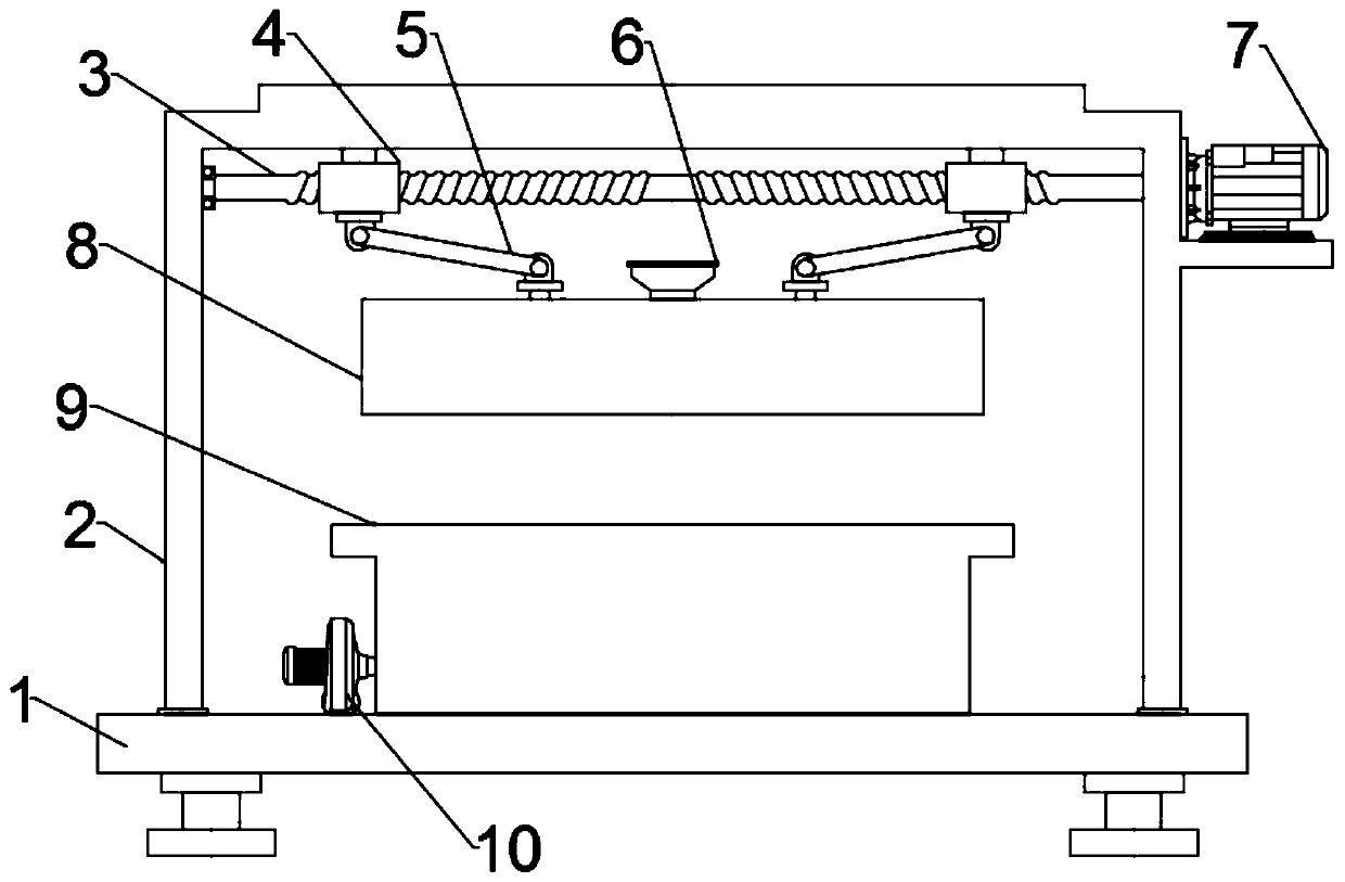
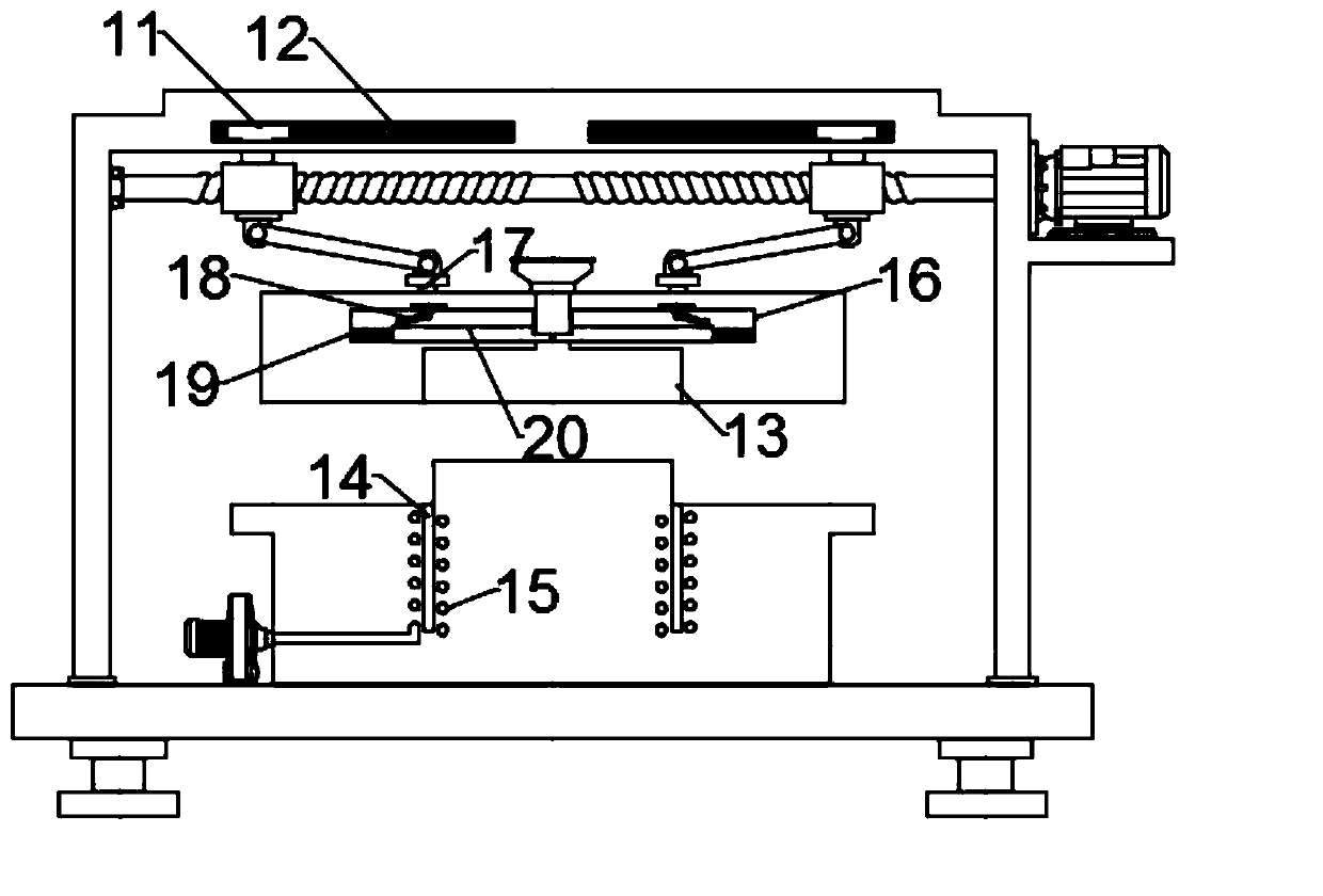
[0023] In an embodiment of the present invention, an injection mold for plastic packaging products includes a bottom plate 1, a bracket 2 fixed on the bottom plate 1, an upper mold 8 connected to a lifting mechanism, and a lower mold 9 fixed on the bottom plate 1; The upper mold 8 is located directly above the lower mold 9, and the lifting mechanism drives the relative lower mold 9 of the upper mold 8 to move up and down. The upper mold 8 is provided with an injection port 6 for injection molding liquid to pour into, and the injection port 6 communicates with the upper mold position 13 arranged in the upper mold 8, and the two sides of the flow channel that the injection port 6 communicates with the upper mold position 13 are symmetrically provided with movable chambers 16, and the inner side of the movable chamber 16 slides through the movable chamber The cutting rod 20 on the side wall of 16, the upper side of the cutting rod 20 away from the flow channel is hinged with the m...

Embodiment 2

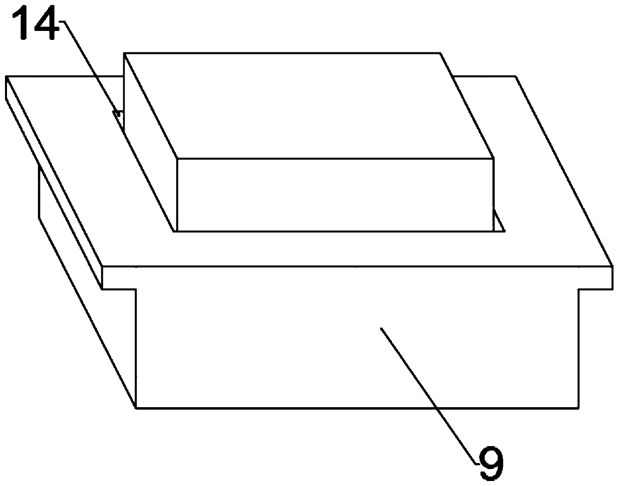
[0031] In order to speed up the cooling of injection molded products, the present invention also proposes another embodiment to improve the present application during the specific implementation process. Specifically, the side end of the lower mold 9 is provided with a fan 10, and the air outlet of the fan 10 is connected with the It communicates with the heat dissipation channel 15 in the lower mold 9, and the fan 10 can effectively accelerate the flow rate of the gas in the heat dissipation channel 15 when working, thereby increasing the cooling of the injection molded product.

[0032] The heat dissipation passages 15 are evenly distributed on the inner and outer ends of the lower mold position 14 to realize simultaneous heat dissipation inside and outside the injection molded product, and the heat dissipation effect is good.


PUM


Abstract

The invention relates to the technical field of injection molding of plastic packaging products, in particular to an injection mold for a plastic packaging product. The injection mold comprises a bottom plate, a support fixed on the bottom plate, an upper mold connected with a lifting mechanism and a lower mold fixed on the bottom plate; the upper mold is located over the lower mold, an injectionport used for pouring injection molding liquid is formed in the upper mold and communicates with an upper mold position arranged in the upper mold, movable cavities are symmetrically formed in the twosides of a runner, communicating with the upper mold position, of the injection port, and cutting rods penetrating through the side walls of the movable cavities slide on the inner sides of the movable cavities; and the upper side of the end, away from the runner, of each cutting rod is hinged to a movable block penetrating through the upper wall of the corresponding movable cavity and connectedwith the lifting mechanism through a second connecting rod. The arranged lifting mechanism drives the movable block to move upwards, and at the moment, the cutting rods move oppositely under the action of the second connecting rods, so that redundant injection molding materials solidified in the upper mold position and the runner are cut off, subsequent cutting treatment is not needed, and use isconvenient.

Description

technical field [0001] The invention relates to the technical field of injection molding of plastic packaging products, in particular to an injection mold for plastic packaging products. Background technique [0002] Plastic packaging refers to packaging in plastic. Plastics are based on synthetic or natural polymer resins. After adding various additives, it has ductility under certain temperature and pressure, and it is a kind of material that can fix its shape after cooling. [0003] Most of the existing box-type plastic packaging products are made of injection molds. Injection molds are a tool for producing plastic products; they are also tools for giving plastic products a complete structure and precise dimensions. Injection molding is a processing method used in the mass production of certain complex-shaped parts. Specifically, it refers to injecting the heated and melted plastic into the mold cavity under high pressure from the injection molding machine, and after c...

Claims


Application Information

Patent Timeline
Patent Type & Authority Applications(China)
IPC IPC(8): B29C45/38B29C45/66B29C45/26B29C45/27B29C45/72
CPCB29C45/2602B29C45/27B29C45/38B29C45/66B29C45/7207
Inventor 不公告发明人
Owner 温州誉诚包装有限公司
Features
  • R&D
  • Intellectual Property
  • Life Sciences
  • Materials
  • Tech Scout
  • Unparalleled Data Quality
  • Higher Quality Content
  • 60% Fewer Hallucinations
Learn More