
New energy automobile charging equipment

A technology for new energy vehicles and charging equipment, which is applied in the direction of electric vehicle charging technology, charging stations, electric vehicles, etc. It can solve the problems of charging equipment not being put back in place, charging equipment is inconvenient to take and place, charging equipment is easily damaged, etc., and achieves an improvement. Safety and longevity, easy access and fixation, easy to put back into place

Inactive Publication Date: 2020-07-31
高跃
View PDF0 Cites 0 Cited by
  • Summary
  • Abstract
  • Description
  • Claims
  • Application Information

AI Technical Summary

Problems solved by technology

[0004] The purpose of the present invention is to solve the inconvenience of taking and placing the existing charging equipment. After use, the charging equipment is easy to be put back in place, resulting in easy loosening, and the lack of a reminder light makes the charging equipment easy to be damaged, and has a certain impact on other users. Potentially dangerous disadvantages, and proposed a new energy vehicle charging equipment

Method used


Image

  • New energy automobile charging equipment
  • New energy automobile charging equipment
  • New energy automobile charging equipment

Examples


Embodiment 1

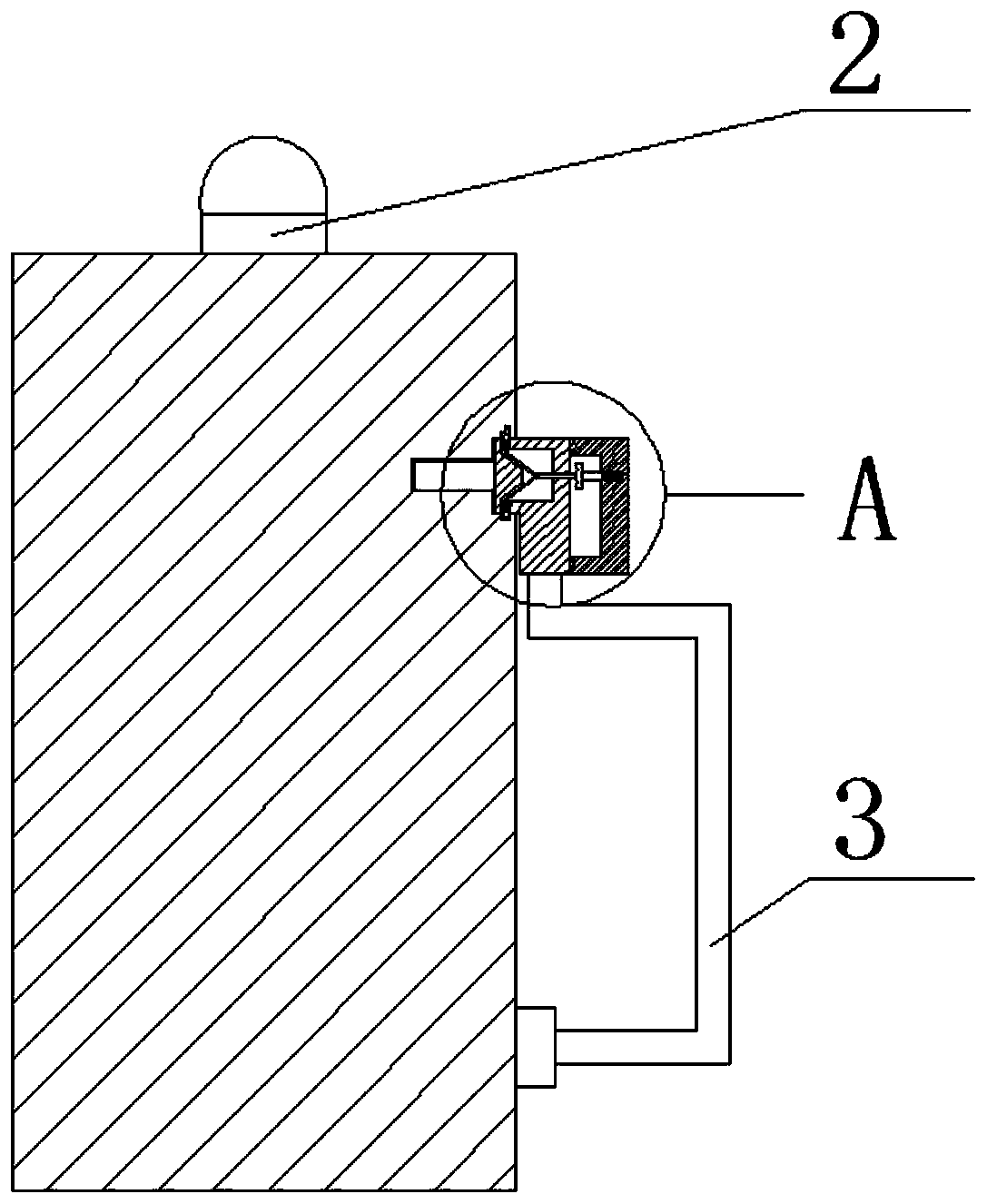
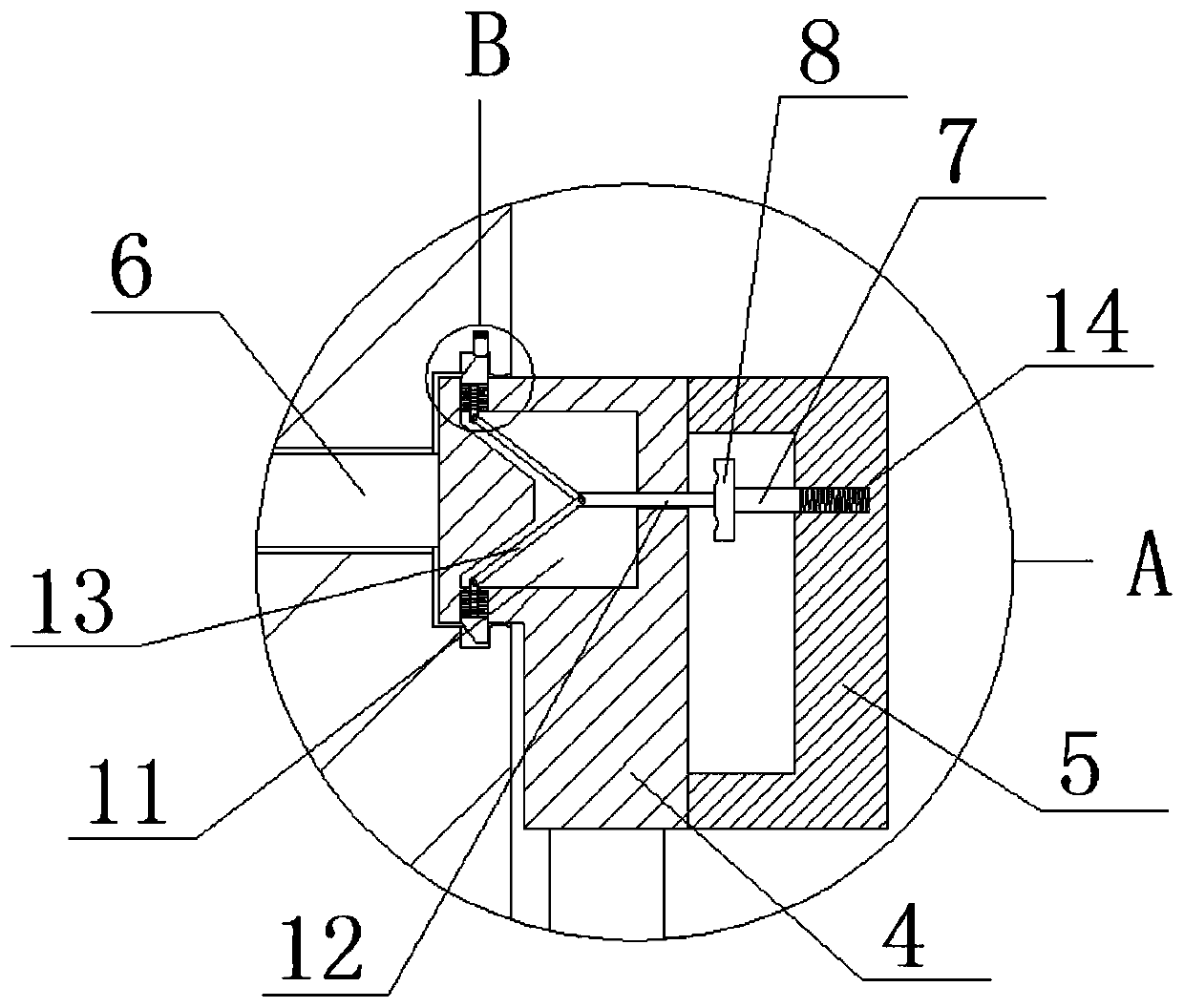
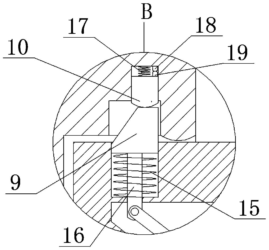
[0017] refer to Figure 1-3 , a new energy vehicle charging device, comprising a charging pile 1, an indicator light 2 is fixedly installed on the top of the charging pile 1, one end of a charging cable 3 is arranged on one side of the charging pile 1, and the other end of the charging cable 3 is fixedly connected to There is a charging stand 4, one side of the charging stand 4 is fixedly connected with a handle 5, the other side of the charging stand 4 is provided with a charging head 6, one side of the charging pile 1 is provided with a first placement slot, and one side of the charging pile 1 is provided with a There is a second placement slot connected with the first placement slot, the second placement slot is matched with the charging head 6, the first placement slot is matched with the charging base 4, a first spring slot is opened on one side of the handle 5, and the second placement slot is matched with the charging head 4. A squeeze rod 7 is slidably installed in a s...

Embodiment 2

[0023] refer to Figure 1-3 , a new energy vehicle charging device, comprising a charging pile 1, the top of the charging pile 1 is fixed with an indicator light 2 by screws, one end of a charging cable 3 is arranged on one side of the charging pile 1, and the other end of the charging cable 3 The charging base 4 is fixedly connected with screws, one side of the charging base 4 is fixedly connected with the handle 5 by welding, the other side of the charging base 4 is provided with a charging head 6, and one side of the charging pile 1 is provided with a first placement slot for charging. One side of the pile 1 is provided with a second placement slot connected with the first placement slot, the second placement slot is matched with the charging head 6, the first placement slot is matched with the charging stand 4, and one side of the handle 5 is provided with a The first spring groove, an extrusion rod 7 is slidably installed in the first spring groove, one side of the extrus...


PUM


Abstract

The invention belongs to the technical field of charging equipment, and particularly relates to new-energy automobile charging equipment. In allusion to the problems that the existing charging equipment is inconvenient to take and place, the charging equipment is not easy to put back in place and prone to loosening after being used and lacks an indicator lamp, and the charging equipment is easy todamage and poses a certain potential danger to other users, the following scheme is proposed: the new-energy automobile charging equipment comprises a charging pile, an indicator lamp is fixedly mounted at the top of the charging pile, one side of the charging pile is provided with one end of a charging cable, the other end of the charging cable is fixedly connected with a charging seat, one sideof the charging seat is fixedly connected with a handle, and the other side of the charging seat is provided with a charging head. By arranging the indicator lamp and the button, the charging equipment is convenient to take, place and use, the charging equipment is easy to put back in place and not prone to loosening after being used, the indicator lamp can be turned on when the charging equipment is not placed in place, the use safety is improved, and the service life is prolonged.

Description

technical field [0001] The invention relates to the technical field of charging equipment, in particular to a new energy vehicle charging equipment. Background technique [0002] With the penetration of green and environmental protection into our lives, low-carbon has become the main theme of my country's economic development, and new energy vehicles have become a vigorously developed industry in my country because they can reduce oil consumption and reduce pollution gas emissions. New energy vehicle charging equipment is a new energy Car driving provides energy supply, which seems to be a necessary supply facility for the development of new energy vehicles; [0003] However, the existing charging equipment is generally powered by the driver himself through manual plugging, which is inconvenient to take and put. And there is a certain potential danger to other users. Contents of the invention [0004] The purpose of the present invention is to solve the inconvenience of t...

Claims


Application Information

Patent Timeline
IPC IPC(8): B60L53/31B60L53/16B60L53/60
CPCB60L53/16B60L53/31B60L53/60Y02T10/70Y02T10/7072Y02T90/12Y02T90/14
Inventor 高跃
Owner 高跃
Features
  • Generate Ideas
  • Intellectual Property
  • Life Sciences
  • Materials
  • Tech Scout
  • Unparalleled Data Quality
  • Higher Quality Content
  • 60% Fewer Hallucinations
Learn More