Corner cutting equipment for PVC template production and machining and working method of corner cutting equipment

A PVC template and cutting equipment technology, applied in metal processing equipment, welding/cutting auxiliary equipment, welding equipment, etc., can solve the problems of dropping, dislocation, inconvenient PVC template fixing and taking out, etc., to achieve easy fixing and taking out, Avoid the effect of dislocation

Pending Publication Date: 2020-06-19
安徽海铭塑业有限公司
View PDF1 Cites 1 Cited by
  • Summary
  • Abstract
  • Description
  • Claims
  • Application Information

AI Technical Summary

Problems solved by technology

[0004] The object of the present invention is to provide a kind of edge cutting equipment and its working method for the production and processing of PVC formwork, and solve the following technical problems: (1) the first screw rod is driven to rotate by the output shaft of the first motor, and the first screw rod cooperates with the first screw rod to rotate. The screw nut drives the translation plate to move, and the translation plate moves along the first slide rail on the beam through the first slider at the bottom, and then drives the installation frame to move to the side away from the connecting beam, and stacks multiple PVC templates on the bottom symmetrical plate On the suction cup, solve the technical problem that the PVC template corner cutting equipment in the prior art is inconvenient to fix and take out the PVC template, and cannot meet the technical problems of PVC template cutting with different thicknesses and quantities; (2) through the contraction of the first cylinder piston rod, Then the centering plate at the bottom is driven up through the connecting seat, the centering plate at the bottom drives the rotating plate to rotate along the central axis through the hexagonal tie rod, and then the rotating plate drives the centering plate at the top down through the hexagonal tie rod on the other side, and the two centering plates The plates move towards each other, and the four limit plates are driven by the symmetrical plate to move towards each other. The suction c

Method used


Image

  • Corner cutting equipment for PVC template production and machining and working method of corner cutting equipment
  • Corner cutting equipment for PVC template production and machining and working method of corner cutting equipment
  • Corner cutting equipment for PVC template production and machining and working method of corner cutting equipment

Examples


Embodiment Construction

[0034] The following will clearly and completely describe the technical solutions in the embodiments of the present invention with reference to the accompanying drawings in the embodiments of the present invention. Obviously, the described embodiments are only some, not all, embodiments of the present invention. Based on the embodiments of the present invention, all other embodiments obtained by persons of ordinary skill in the art without creative efforts fall within the protection scope of the present invention.

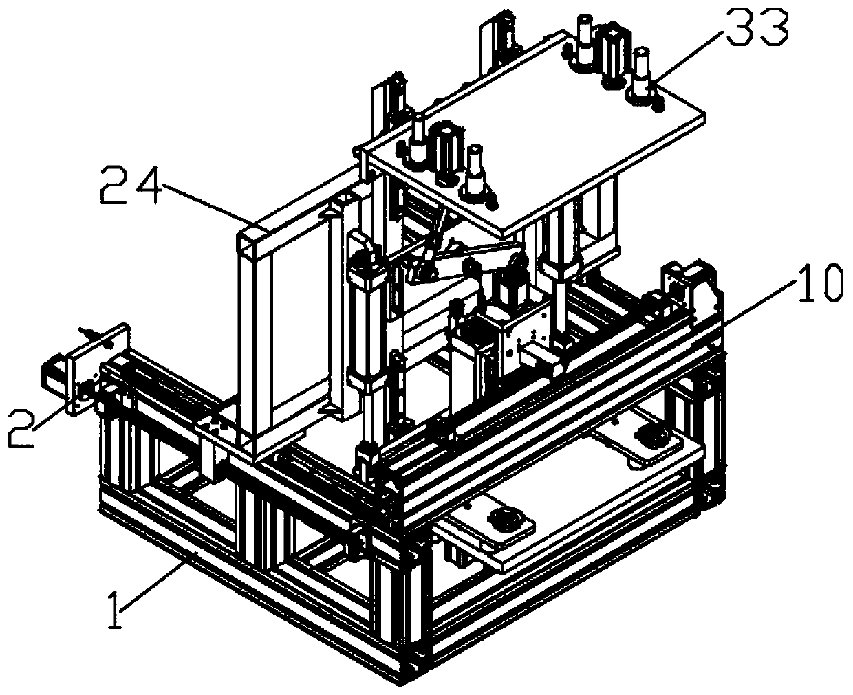
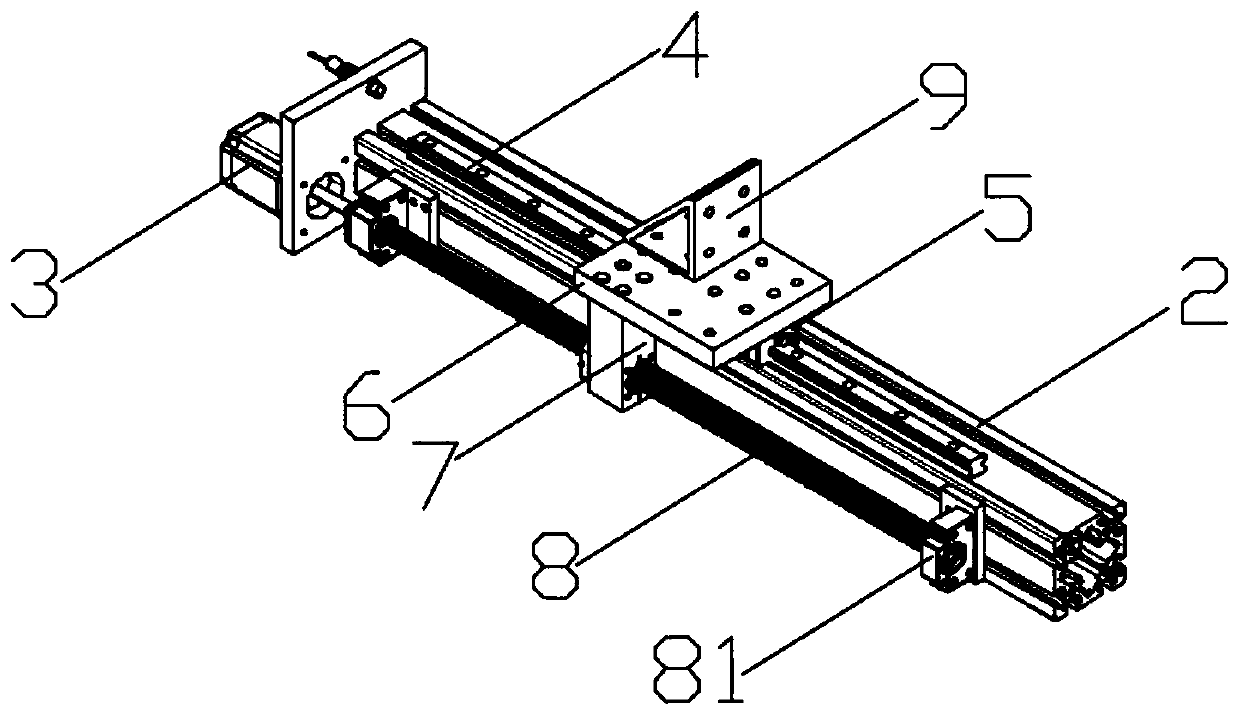
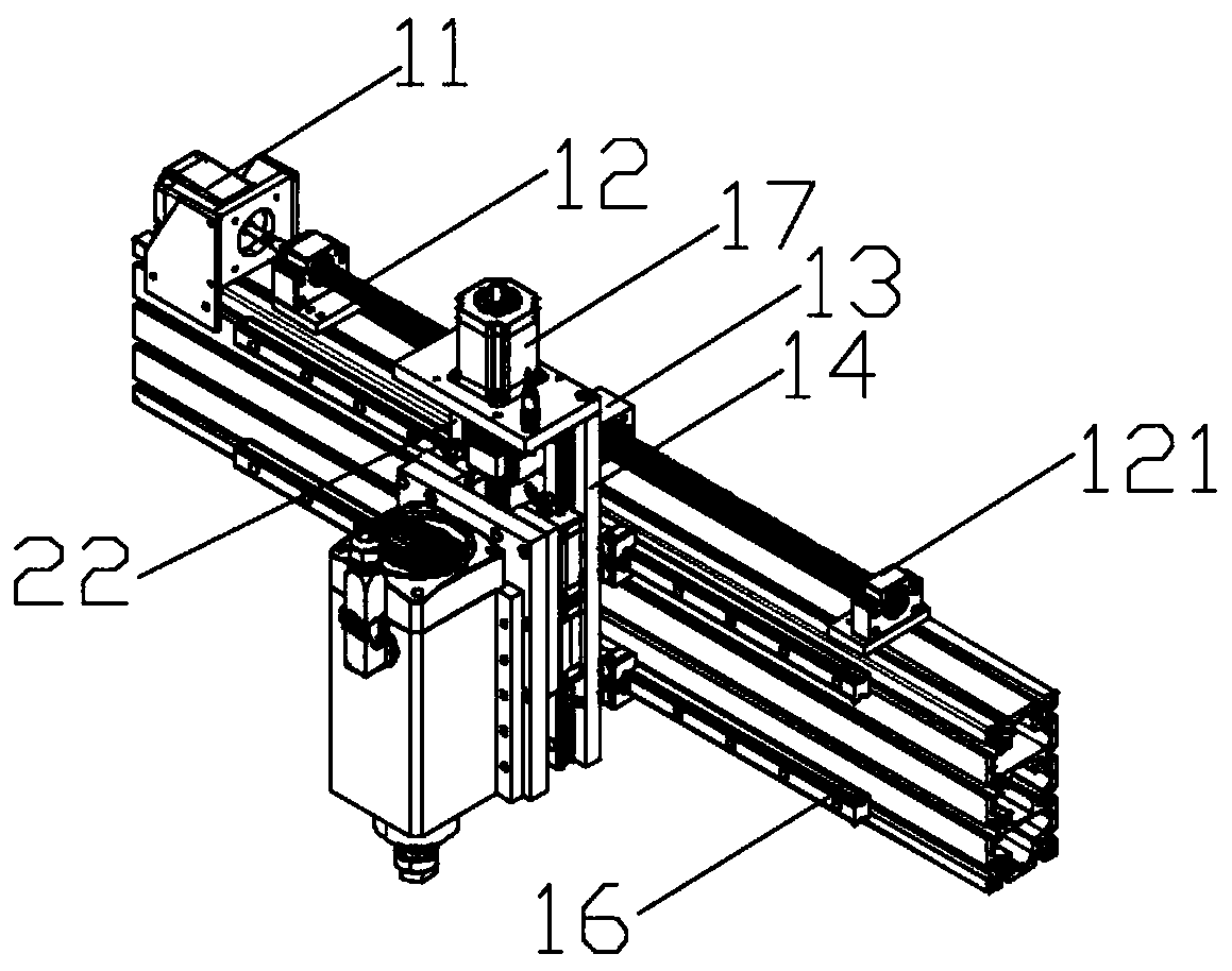
[0035] see Figure 1-8 As shown, the present invention is a corner cutting equipment for the production and processing of PVC formwork, including a chassis 1, a beam 2 is installed on both sides of the chassis 1, a translation plate 6 is slidingly installed on the top of the beam 2, and the bottom side of the translation plate 6 is The first screw nut 7 is installed, the first screw nut 7 is rotated and sleeved on the outer peripheral surface of the first screw 8, ...


PUM


Abstract

The invention discloses corner cutting equipment for PVC template production and machining and a working method of the corner cutting equipment. The corner cutting equipment comprises an underframe. Cross beams are mounted on the two sides of the underframe. A translation plate is mounted at the top of each cross beam in a sliding manner. A first lead screw nut is mounted on one side of the bottomof each translation plate. Each first lead screw nut is rotationally arranged on the peripheral face of a first lead screw in a sleeving manner. Each first lead screw is mounted on one side of the corresponding cross beam, and one end of each first lead screw is connected with an output shaft of a first motor. The first lead screws are driven by the output shafts of the first motors to rotate, the first lead screws cooperate with the first lead screw nuts to drive the translation plates to move, the translation plates move along first sliding rails on the cross beams through first sliding blocks at the bottoms, then a mounting rack is driven to move to the side away from a connecting beam, multiple PVC templates are stacked on suction cups of bottom symmetric plates, and the technical problems that in the prior art, in corner cutting equipment for PVC templates, PVC templates are inconvenient to fix and take out, and cutting of PVC templates of different thicknesses and numbers cannotbe met are solved.

Description

technical field [0001] The invention relates to the technical field of PVC template production and processing, in particular to a corner cutting device for PVC template production and processing and a working method thereof. Background technique [0002] As a building material, building formwork is widely used in the field of construction. At present, most of the traditional building formworks use steel formwork, bamboo and wood formwork, etc. The traditional steel formwork becomes relatively cumbersome due to its heavy weight, and in the case of a large amount of use, the investment is large and the maintenance cost is high. In the process of processing bamboo and wood formwork, there is a lot of material waste, resulting in a large investment, and in the process of use, it is easy to be deformed due to external influences. Nowadays, PVC formwork is more and more widely used in the construction field, and the production and processing of PVC formwork does not ensure the ac...

Claims


Application Information

Patent Timeline
IPC IPC(8): B23K26/38B23K26/70B23K26/08B23K37/04
CPCB23K26/0869B23K26/38B23K26/702B23K37/0408B23K2101/18B23K2103/42
Inventor 张海侠张涛
Owner 安徽海铭塑业有限公司
Why Eureka
Try Eureka