Weldless small box girder wet joint structure and method adopting ultra-high performance concrete

An ultra-high performance, small box girder technology, applied in bridges, bridge materials, bridge construction, etc., can solve the problems of high engineering labor cost and time cost, poor on-site welding quality of embedded steel bars, and inability to guarantee construction quality. The effect of saving labor cost and time cost, reducing on-site construction workload, and reducing on-site construction procedures

Inactive Publication Date: 2020-07-31
TIANJIN MUNICIPAL ENG DESIGN & RES INST
View PDF10 Cites 8 Cited by
  • Summary
  • Abstract
  • Description
  • Claims
  • Application Information

AI Technical Summary

Problems solved by technology

[0004] When this connection method is applied to large-scale prefabricated concrete small box girders, there will be the following problems: (1) the welding workload of wet joint lapped steel bars is huge, and the labor cost and time cost of the project are high; (2) pre-embedded The on-site welding quality of the steel bars is poor. When the position deviation of the steel bars reserved for the bridge deck is difficult to correct on site, the construction process is cumbersome and the construction quality cannot be guaranteed.

Method used


Image

  • Weldless small box girder wet joint structure and method adopting ultra-high performance concrete
  • Weldless small box girder wet joint structure and method adopting ultra-high performance concrete
  • Weldless small box girder wet joint structure and method adopting ultra-high performance concrete

Examples


Embodiment Construction

[0035] In order to further understand the invention content, characteristics and effects of the present invention, the following examples are given, and detailed descriptions are as follows in conjunction with the accompanying drawings:

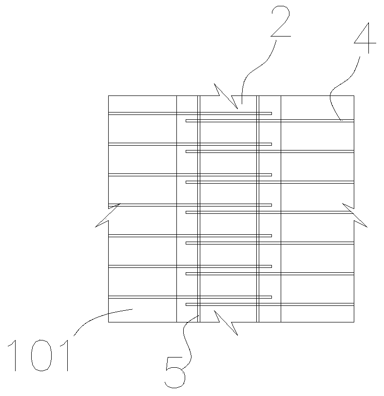
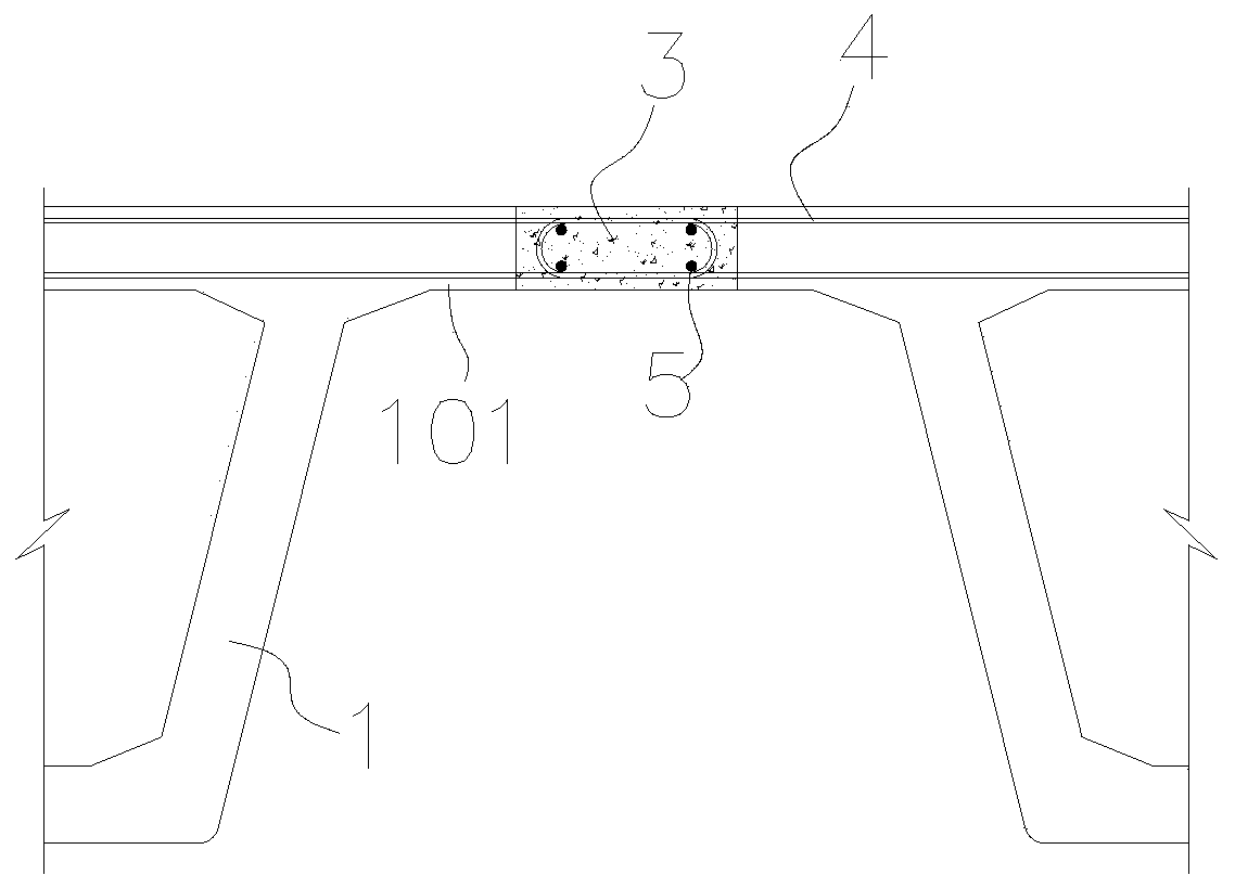
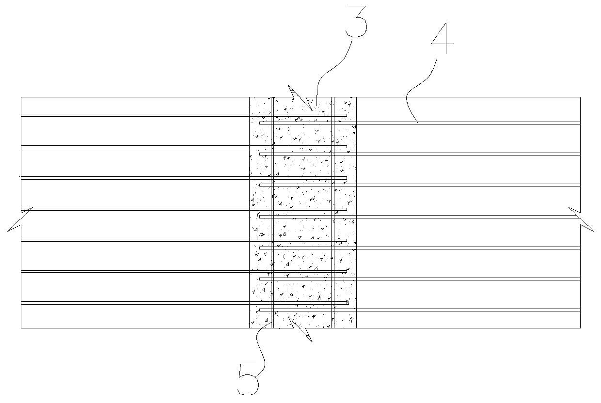
[0036] as attached Figure 1 to Figure 5 As shown, a non-welded small box girder wet joint structure using ultra-high performance concrete 3 includes multiple prefabricated small box girders 1 .

[0037] The prefabricated small box girder 1 is a prefabricated concrete small box girder. Each of the prefabricated small box girders 1 is arranged along the bridge direction, and a plurality of the prefabricated small box girders 1 are arranged in parallel in the transverse bridge direction, and are formed at intervals between two adjacent prefabricated small box girders 1 Wet seams along the bridge 2.

[0038] The top of the prefabricated small box girder 1 is provided with a bridge deck straight section 101 near the side of the wet joint 2, and...


PUM


Abstract

The invention discloses an ultra-high performance concrete wet joint structure with prefabricated small box girders and a construction method of the ultra-high performance concrete wet joint structure. The wet joint structure comprises a plurality of prefabricated small box girders, wherein each prefabricated small box girder is arranged along the bridge direction, and a wet joint along the bridgedirection is formed between two adjacent prefabricated small box girders; a bridge deck slab straight section is arranged at the top of the prefabricated small box girder, a plurality of annular reinforcing steel bars are pre-buried in the bridge deck slab straight section, each annular reinforcing steel bar is arranged in the transverse bridge direction, and the annular ends of the annular reinforcing steel bars extend into the wet joints; a plurality of constructional steel bars are arranged in the wet joint, and each constructional steel bar is arranged in the bridge direction; ultra-high-performance concrete is poured into the wet joints, the constructional steel bars and the annular steel bars extending into the wet joints are wrapped in the ultra-high-performance concrete, and everytwo adjacent small prefabricated box girders are connected into a whole through the ultra-high-performance concrete of the wet joints and the annular steel bars wrapped in the ultra-high-performanceconcrete. According to the invention, the construction procedure can be simplified, the construction efficiency is improved, the manufacturing cost is reduced, and the construction quality is effectively improved.

Description

technical field [0001] The invention relates to bridge structure technology, in particular to an ultra-high performance concrete (UHPC) wet joint structure of a prefabricated small box girder and a construction method thereof. Background technique [0002] In the field of bridge construction, precast concrete small box girders are widely used in bridge construction in my country. The design methods and construction techniques are mature. Precast concrete small box girders have the characteristics of fast construction speed and high degree of industrialization. Wet joints should be reserved between two prefabricated small box girders. The wet joint structure must be able to accurately transmit internal forces such as bending moment and shear force, and it is also an important structure to ensure the overall mechanical performance of the structure. [0003] In the traditional wet joint structure of precast concrete small box girders, pre-embedded annular connecting bars are mo...

Claims


Application Information

Patent Timeline
Patent Type & Authority Applications(China)
IPC IPC(8): E01D2/04E01D19/00E01D101/24
CPCE01D2/04E01D19/00E01D2101/24
Inventor 高庆峰李焱张鹏谢斌田川杜鹏陈龙周莉熊军孙东利刘旭锴张洪海武建敏赵聚成祁永利高应振李伟金波
Owner TIANJIN MUNICIPAL ENG DESIGN & RES INST
Why Eureka
Try Eureka