Heat supply pipeline connecting structure and construction method thereof

A technology for connecting structures and heating pipes, which is applied in the directions of pipe supports, pipe laying and maintenance, pipes/pipe joints/fittings, etc. The effect of a small load

Active Publication Date: 2020-07-31
XIAN COAL CONSTR ENG
View PDF11 Cites 8 Cited by
  • Summary
  • Abstract
  • Description
  • Claims
  • Application Information

AI Technical Summary

Problems solved by technology

[0004] However, the connectors in the above-mentioned prior art solutions can only be used for buffering and shock absorption between two adjacent heating pipes, but cannot protect the heating pipes that have a tendency to crack or have cracks, preventing crack growth

Method used


Image

  • Heat supply pipeline connecting structure and construction method thereof
  • Heat supply pipeline connecting structure and construction method thereof
  • Heat supply pipeline connecting structure and construction method thereof

Examples


Embodiment 1

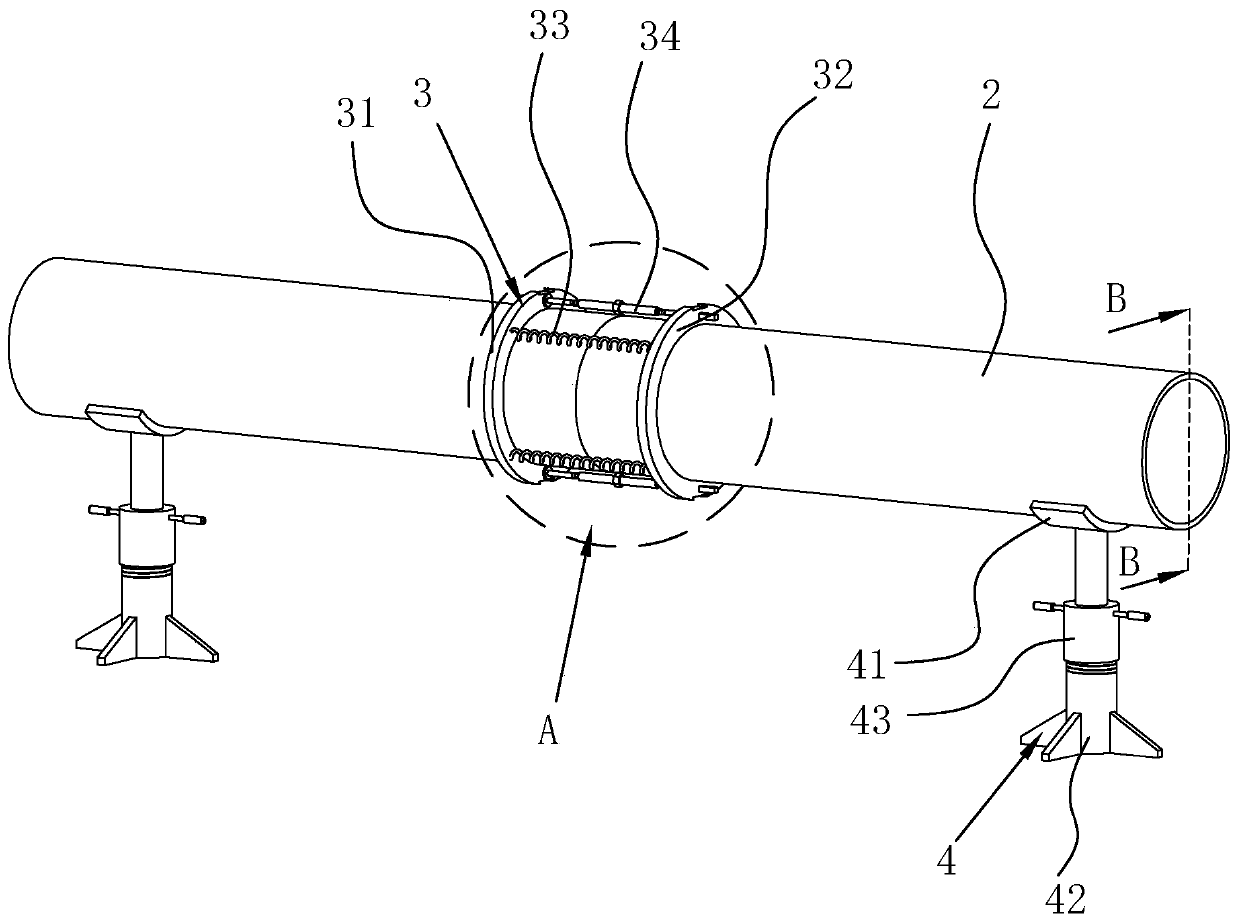
[0055] refer to figure 1 , is a connection structure for heating pipes disclosed in this embodiment of the present invention, including several pipes 2 connected end to end, a connecting piece 3 arranged between two adjacent pipes 2 and a prefabricated pipe supported under the two ends of the pipes 2. The support 4, the pipeline 2, the connector 3 and the outside of the preset support all have fillers, and the top of the filler is flush with both sides of the upper end of the groove 1.

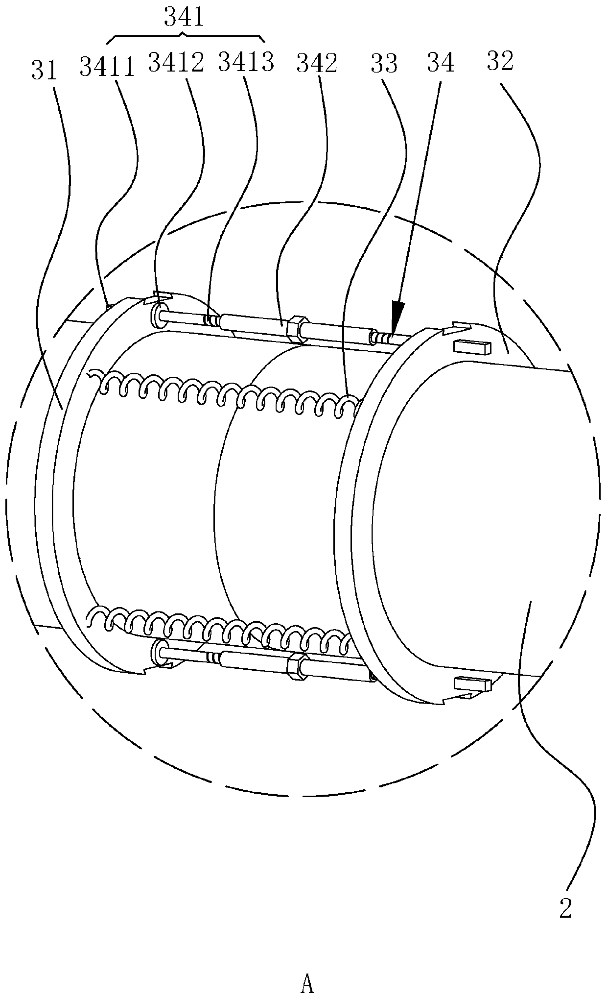
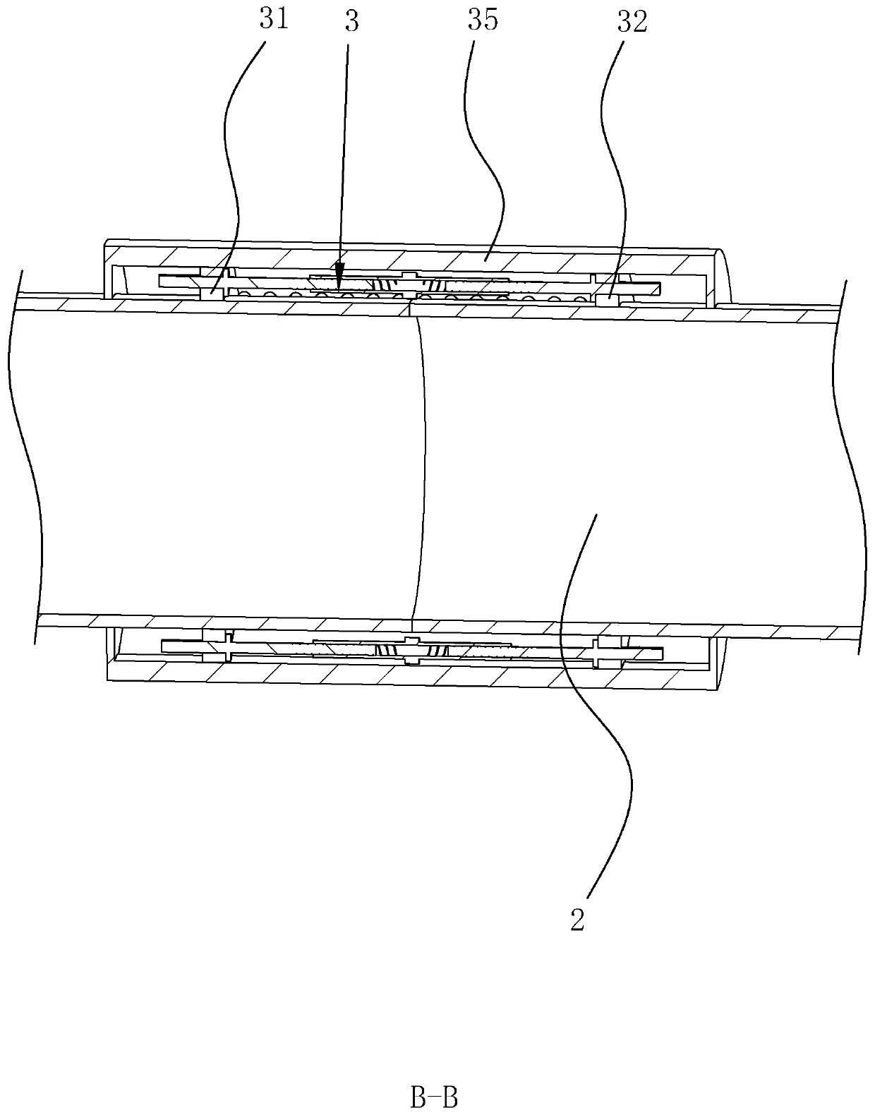
[0056] refer to figure 2 , image 3 , the connector 3 in this embodiment includes a first connecting ring 31, a second connecting ring 32, at least three elastic members 33 and at least two struts arranged between the first connecting ring 31 and the second connecting ring 32 34. The first connecting ring 31 and the second connecting ring 32 are coaxially connected to two adjacent pipes 2 respectively. When the connecting piece 3 is in use, the elastic member 33 has the function of connecti...

Embodiment 2

[0063] This embodiment of the present invention discloses a construction method suitable for the heating pipeline connection structure disclosed in Embodiment 1, which includes the following steps:

[0064] S1: Measurement and setting out: According to the terrain and landform, measure the buried position and direction of the pipeline 2, and mark the setting out, and mark the positions of the prefabricated support 4 and the spreader according to the length and curvature of the pipeline 2.

[0065] S2: Excavation of trench 1: According to the measurement results and the setting-out position, trench 1 is excavated to reach the design elevation and standard width, and trench 1 is opened at a position 225-30cm higher than the preset pipeline with a step groove 11 whose width is greater than that at the bottom .

[0066] S3: Cleaning and tamping: Level the bottom of the tank, clean up the sundries at the bottom of the tank, and tamp the bottom of the tank to a degree of no less tha...


PUM


Abstract

The invention discloses a heat supply pipeline connecting structure and a construction method thereof, and relates to the technical field of heat supply pipeline laying. The heat supply pipeline connecting structure comprises pipelines connected end to end, a connecting part arranged between every two adjacent pipelines and prefabricated supports arranged below the two ends of the pipelines. Eachconnecting part comprises a first connecting ring, a second connecting ring, at least three elastic parts and at least two supporting rods, wherein the elastic parts and the supporting rods are arranged between the first connecting ring and the second connecting ring, and the first connecting ring and the second connecting ring are connected to the adjacent pipelines correspondingly. In a use state of the connecting parts, the elastic parts have the trend of pulling the first connecting rings and the second connecting rings to be close. The construction method of the heat supply pipeline connecting structure includes the steps of measuring and setting-out, groove digging, cleaning, tamping, primary back-filling, pipeline hoisting, welding of the connecting parts, welding of the pipelines,taking down of the supporting rods, pipeline testing, sleeving of protective sleeves and earthwork back-filling. The heat supply pipeline connecting structure and the construction method thereof havethe beneficial effect of preventing weld joints at the joints of the pipelines from cracking.

Description

technical field [0001] The invention relates to the technical field of heating pipeline laying, in particular to a heating pipeline connection structure and a construction method thereof. Background technique [0002] At present, the pipelines of central heating projects in cities and industrial and domestic heating equipment used by large and medium-sized enterprises are mostly directly buried underground, which is the so-called direct buried heating pipeline. Most of the existing heating pipeline connections are rigid connections. When the pipeline is shaken, it will cause damage and it is difficult to recover automatically. Therefore, it is necessary to improve the design of the connection to prevent permanent damage to the heating pipeline caused by the earthquake. [0003] The above-mentioned technical problems are not solved, and the utility model with the notification number CN207049518U discloses an anti-seismic thermal insulation heating pipeline, including an outer...

Claims


Application Information

Patent Timeline
Patent Type & Authority Applications(China)
IPC IPC(8): F16L1/036F16L1/11F16L3/02F16L3/20
CPCF16L1/036F16L1/11F16L3/02F16L3/20
Inventor 侯相群李由
Owner XIAN COAL CONSTR ENG
Why Eureka
Try Eureka