
Ultra-high pressure gas pipeline push-in joint with protection device and operation method thereof

A technology for gas pipelines and protective devices, applied in mechanical equipment, couplings, etc., can solve the problems of cumbersome plugging and unplugging process, poor applicability, low safety and reliability, etc., to avoid high-speed throwing off and splashing, easy to operate and use , good sealing effect

Active Publication Date: 2021-11-02
HEFEI GENERAL MACHINERY RES INST
View PDF0 Cites 1 Cited by
  • Summary
  • Abstract
  • Description
  • Claims
  • Application Information

AI Technical Summary

Problems solved by technology

Due to the lack of relevant national standards, the push-in joints used in the existing ultra-high pressure pipeline system are mainly improved on the basis of the 40MPa high-pressure pipe joint standard. In addition to the problems of complex processing and manufacturing processes, poor applicability, and low safety and reliability , but also faced with the status quo that it cannot be plugged and unplugged under pressure, resulting in a cumbersome plugging process and a complicated process
In addition, when the ultra-high pressure push-in joints used at this stage control the connection or separation of the ultra-high pressure source and the ultra-high pressure pipeline, due to the very high medium pressure in the pipeline, if the seal of the ultra-high pressure push-in joint fails or is caused by improper operation When the residual ultra-high pressure medium exists, it is very easy to cause high-speed throwing off and splashing of the movable end joint, causing serious losses to operators and field equipment, and there is a great potential safety hazard

Method used


Image

  • Ultra-high pressure gas pipeline push-in joint with protection device and operation method thereof
  • Ultra-high pressure gas pipeline push-in joint with protection device and operation method thereof
  • Ultra-high pressure gas pipeline push-in joint with protection device and operation method thereof

Examples


Embodiment Construction

[0047] For ease of understanding, the specific structure and working method of the present invention are further described as follows:

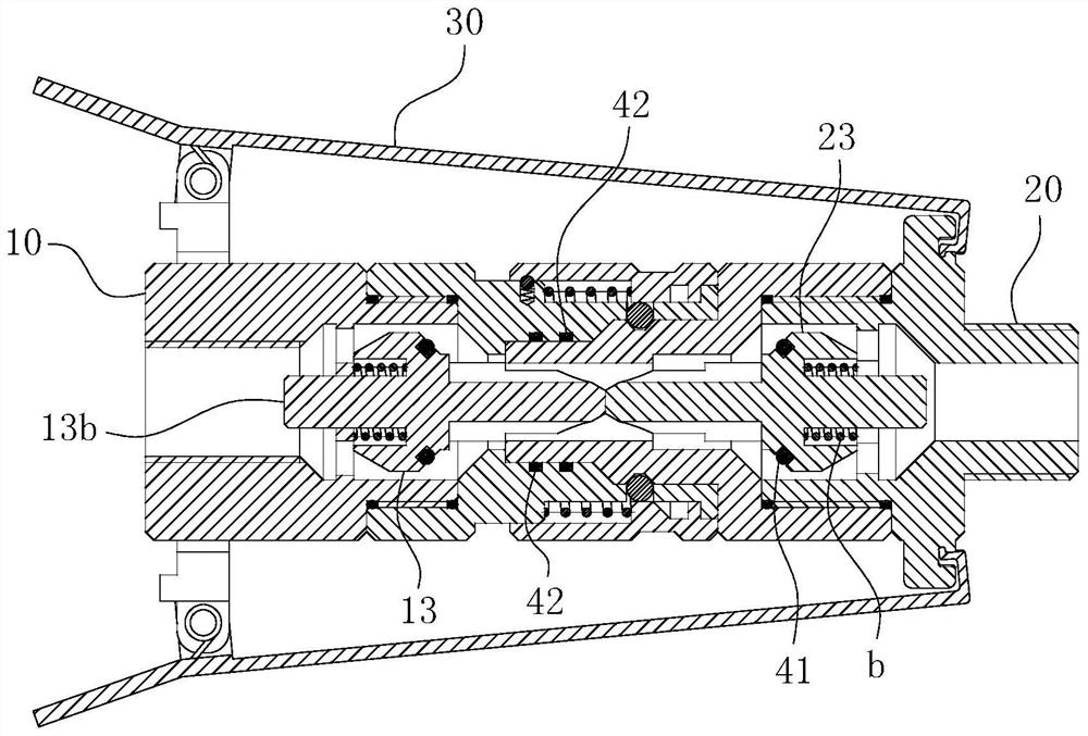
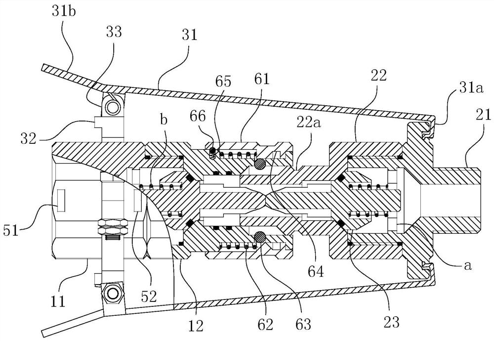
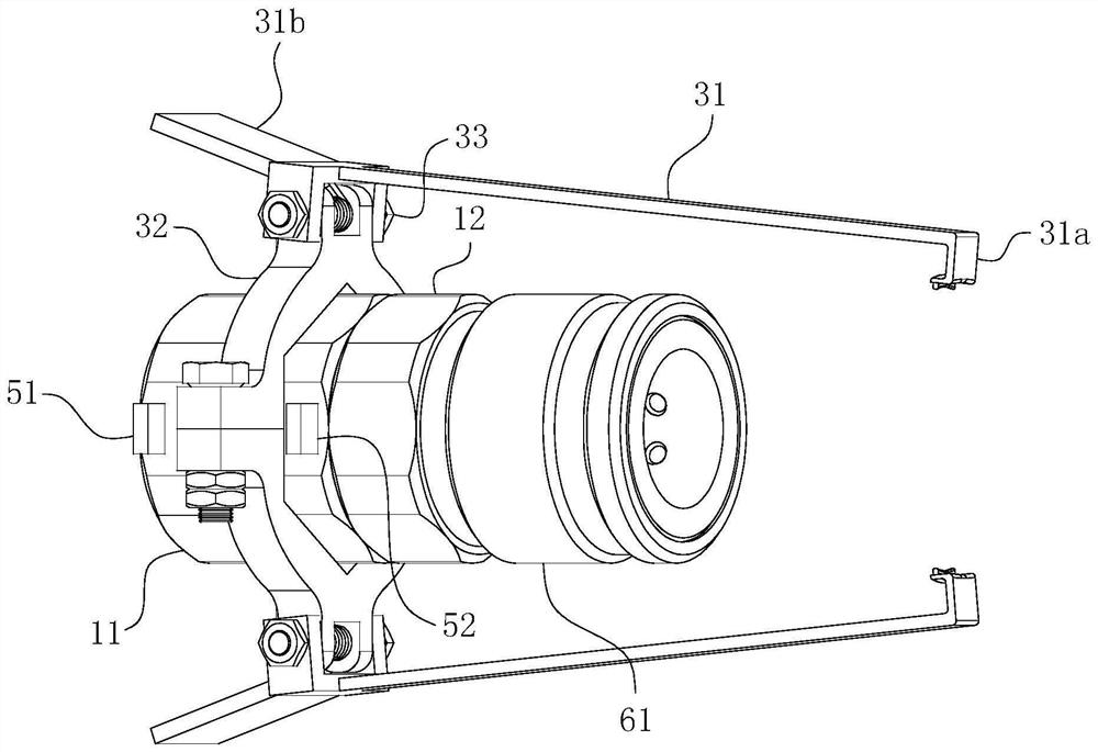
[0048] The concrete implementation structure of the present invention can refer to Figure 1-8 As shown, the main body includes a fixed end assembly 10 , a movable end assembly 20 and a protection assembly 30 , wherein the protection assembly 30 mainly includes a protection card arm 31 , a slip ring 32 , a hinge seat 33 and an anchor point 34 . in such as Figure 1-3 It can be seen from the figure that the slip ring 32, the hinge seat 33 and the protection arm 31 form a combined structure and fit on the fixed end assembly 10, while the anchor point 34 is as shown in Figure 4 The self-contained structure shown fits on the movable end assembly 20 . In actual operation, both the fixed end assembly 10 and the movable end assembly 20 can independently and reliably seal the medium in the connected system during independent placement. When the t...


PUM


Abstract

The invention relates to the technical field of connection equipment for ultra-high pressure gas pipelines, in particular to a quick-plug connector for ultra-high pressure gas pipelines with a protection device and an operating method thereof. The ultra-high pressure gas pipeline push-in joint with protection device includes a fixed end assembly, a movable end assembly and a protection card arm. The anchor points form a fixed fit relationship; the push-in joint also includes a limit component for limiting the maximum axial displacement action distance of the protection card arm. The invention can not only realize the function of online plugging and unplugging under pressure by hand, but also have extremely high use safety and operation reliability, so that it is suitable for use in ultra-high pressure gas pipelines. Another object of the present invention is to provide an operation method based on the above-mentioned ultra-high voltage push-in connector, so as to realize the purpose of free-hand plugging under pressure more conveniently and safely, including the docking step and the separation step.

Description

technical field [0001] The invention relates to the technical field of connection equipment for ultra-high pressure gas pipelines, in particular to a quick-plug connector for ultra-high pressure gas pipelines with a protection device and an operating method thereof. Background technique [0002] Ultra-high pressure push-in connectors are widely used in the connection of ultra-high pressure gas pipelines. When connecting the pipelines, the connection or disconnection of the pipelines can be realized without the use of other tools. Its working pressure exceeds 70MPa. It is an ultra-high pressure pipeline system An important part of the connection that has a major impact on the safety and reliability of the system. Due to the lack of relevant national standards, the push-in joints used in the existing ultra-high pressure pipeline system are mainly improved on the basis of the 40MPa high-pressure pipe joint standard. In addition to the problems of complex processing and manufact...

Claims


Application Information

Patent Timeline
Patent Type & Authority Patents(China)
IPC IPC(8): F16L37/32F16L37/23
CPCF16L37/23F16L37/32
Inventor 章茂森李忠靳淑军江海龙程红晖陶国庆范宜霖雷艳
Owner HEFEI GENERAL MACHINERY RES INST
Learn More