
A light and shadow flow led wall washer light

A technology of LED wall washer and LED light group, applied in the direction of light source, electric light source, fixed light source, etc., can solve the problems of monotonous lighting effect and high cost

Active Publication Date: 2021-05-14
东莞市佰特照明科技有限公司
View PDF6 Cites 0 Cited by
  • Summary
  • Abstract
  • Description
  • Claims
  • Application Information

AI Technical Summary

Problems solved by technology

[0005] The purpose of the present invention is to provide a light and shadow flowing LED wall washer with good lighting effect and low cost for the above problems of monotonous lighting effect and high cost

Method used


Image

  • A light and shadow flow led wall washer light
  • A light and shadow flow led wall washer light
  • A light and shadow flow led wall washer light

Examples


Embodiment 1

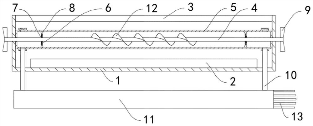
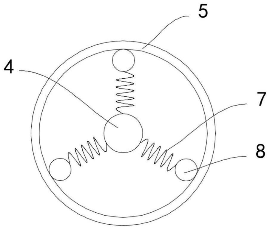
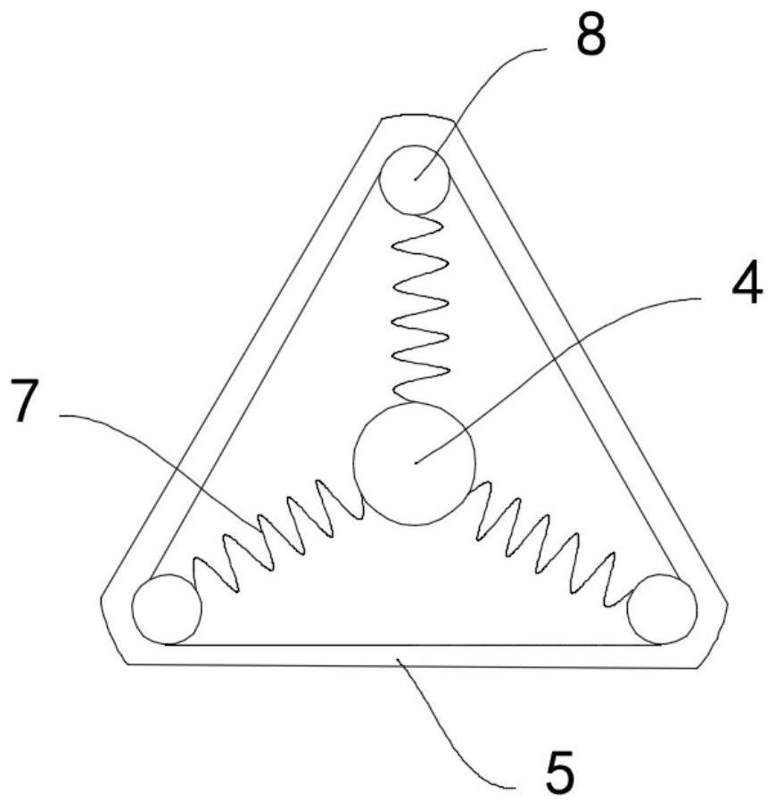
[0019] Such as Figure 1-3 As shown, a light and shadow flow type LED wall washer includes a housing 1, the housing 1 is provided with an LED lamp group 2, the upper surface of the housing 1 is opened and fixed with a dustproof plate 3, the housing 1 Rotating shaft 4 is connected to the inner side wall of the rotating shaft 4, and a deformation tube 5 is coaxially sleeved outside the rotating shaft 4. The deformation tube 5 is made of a flexible transparent material. It includes three return springs 7 distributed circumferentially on the side wall of the rotating shaft 4, the other end of the returning spring 7 is fixedly connected with a counterweight ball 8, and the counterweight ball 8 is fixedly connected with the inner side wall of the deformation tube 5, and the two ends of the rotating shaft 4 are A fan wheel 9 runs through the side wall of the casing 1 and is coaxially fixedly connected thereto.

[0020] Both sides of the deformation tube 5 are fixedly connected with ...

Embodiment 2

[0024] Such as Figure 4 As shown, the difference between this embodiment and Embodiment 1 lies in that: the cooling liquid is doped with magnetic powder, and a piezoelectric sheet 14 is installed between the weight ball 8 and the inner wall of the deformation tube 5 .

[0025] In this embodiment, when the counterweight ball 8 rotates faster, the centrifugal force it receives is greater, and the pressure generated on the piezoelectric sheet 14 is greater, and the piezoelectric sheet 14 converts mechanical deformation into electric current, and with the counterweight The rotation speed of the ball 8 changes, and the current generates a magnetic field and attracts the magnetic powder to move, driving the magnetic powder to flow in the cooling liquid, forming a shadow that changes from time to time, making the irradiation effect of the wall washer more diverse.


PUM


Abstract

The invention belongs to the field of LED lamps, and in particular relates to a light and shadow flowing LED wall washer lamp, which includes a housing, an LED lamp group is arranged inside the housing, and a dustproof plate is fixedly installed on the upper surface of the housing. The inner wall of the housing is rotatably connected with a rotating shaft, and a deformation tube is coaxially sleeved outside the rotating shaft. The deformation tube is made of flexible transparent material, and two sets of support members are fixedly installed on the side wall of the rotating shaft. , the supporting member includes three return springs circumferentially distributed on the side wall of the rotating shaft, the other end of the returning spring is fixedly connected with a weight ball, and the balance ball is fixedly connected with the inner side wall of the deformation tube, and the rotating shaft Both ends of the deformation tube pass through the side wall of the housing and are coaxially fixedly connected with a fan wheel, and both sides of the deformation tube are fixedly connected with a unidirectional flow tube. The invention can flow the cooling liquid so that when the light is irradiated on the surface of the wall, flowing light and shadows changing like water flow are produced, which greatly improves the ornamental effect.

Description

technical field [0001] The invention belongs to the field of LED lamps, in particular to a light and shadow flowing LED wall washer lamp. Background technique [0002] LED wall washer makes the light wash the wall like water. It is mainly used for architectural decoration lighting, and it is also used to outline the outline of large buildings. Because LED has the characteristics of energy saving, high luminous efficiency, rich colors, and long life. , thus being widely used. [0003] However, the current wall washer is generally static, and the light projected on the exterior wall of the building is very monotonous, and the viewing effect is limited. In order to form a dynamic light and shadow effect, most of them are realized by the method of program-controlled lamp head. The color and lighting of the lamp head are controlled through the program. Angle, range, so as to form a changing lighting effect, but the cost of this solution is high, not easy to maintain, so it is di...

Claims


Application Information

Patent Timeline
Patent Type & Authority Patents(China)
IPC IPC(8): F21S10/00F21V13/00F21V14/00F21V14/06F21V29/56F21V29/74F21V29/67F21W131/107F21Y115/10
CPCF21S10/00F21S10/002F21V13/00F21V14/00F21V14/06F21W2131/107F21V29/56F21V29/67F21V29/74F21Y2115/10
Inventor 吴巨才
Owner 东莞市佰特照明科技有限公司
Learn More