Eureka AIR delivers breakthrough ideas for toughest innovation challenges, trusted by R&D personnel around the world.

Feed cutting device

A technology of shredding device and feed, which is applied in cutting equipment, agricultural machinery and implements, applications, etc., can solve the problems of difficult positioning, high processing cost, and damage to the roller or roller, and achieves difficult positioning and processing costs. high effect

Active Publication Date: 2020-08-04
INST OF BAST FIBER CROPS CHINESE ACADEMY OF AGRI SCI
View PDF7 Cites 0 Cited by
  • Summary
  • Abstract
  • Description
  • Claims
  • Application Information

AI Technical Summary

Problems solved by technology

[0005] The technical problem to be solved by the present invention is to provide a feed chopping device, the rollers are easy to disassemble and the distance between the rollers can be adjusted, and the rollers in the prior art are not easy to assemble and disassemble, the positioning is difficult, and the processing cost is high , and due to the way of fixed installation, the distance between the rollers cannot be adjusted. When too much feed is fed at one time, the upper and lower rollers will bear a large load, which is likely to cause damage to the rollers or rollers

Method used


Image

  • Feed cutting device
  • Feed cutting device
  • Feed cutting device

Examples


Embodiment Construction

[0039] In order to enable those skilled in the art to better understand the technical solutions in the present application, the technical solutions in the embodiments of the present application will be clearly and completely described below in conjunction with the drawings in the embodiments of the present application. Obviously, the described The embodiments are only some of the embodiments of the present application, but not all of them.

[0040] In the description of the present application, it should be noted that when an element is referred to as being "fixed" or "disposed on" another element, it can be directly on another element or be indirectly arranged on another element; when an An element is said to be "connected to" another element, either directly or indirectly.

[0041] It is to be understood that the terms "length", "width", "top", "bottom", "front", "rear", "left", "right", "vertical", "horizontal", "top", The orientation or positional relationship indicated b...


PUM


Abstract

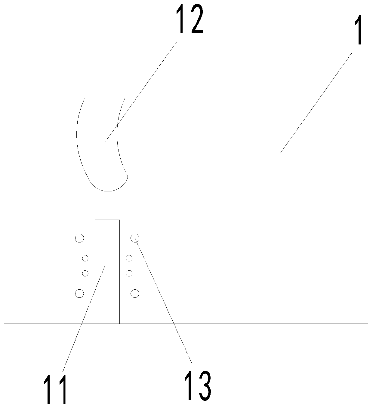
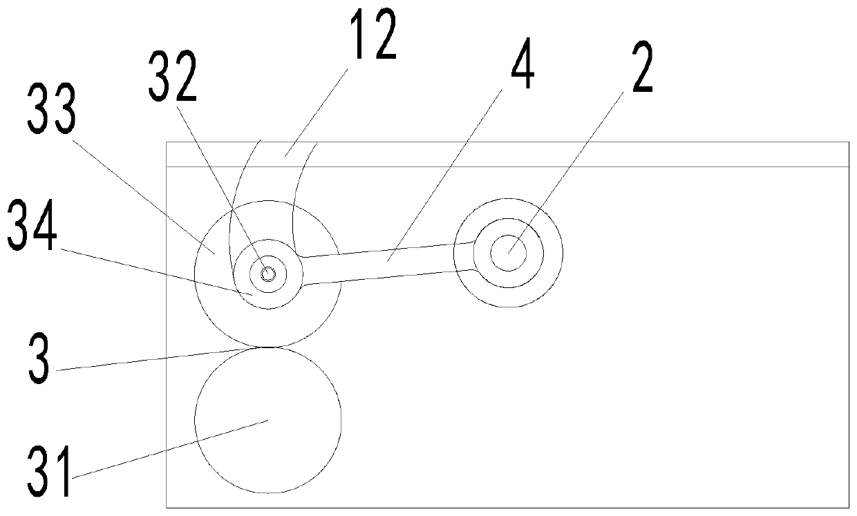
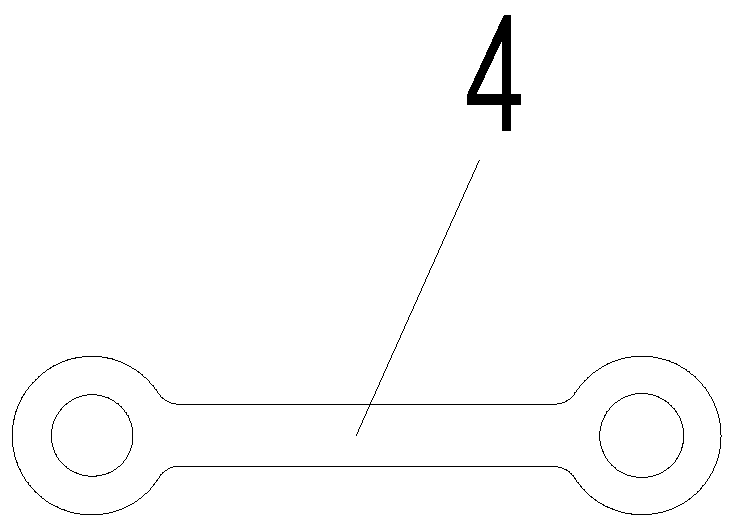
The invention discloses a feed cutting device. The feed cutting device comprises two side plates symmetrically arranged on a rack, a middle shaft arranged between the two side plates; a roller assembly arranged on one side of the middle shaft, a rocker arm mechanism connected with the middle shaft and the roller assembly and guide parts matched with the outer diameter of a roller shaft, wherein afirst guide groove, a first arc groove and a mounting position arranged near the end of the first guide groove are formed in each side plate, and at least two mounting holes are formed around each mounting position; the roller assembly comprises a lower roller fixed to the corresponding side plate, the roller shaft is arranged above the lower roller, and an upper roller is arranged on the roller shaft in a sleeved manner; and the guide parts can slide in the first arc grooves. According to the feed cutting device, rollers are convenient to mount and dismount, the distance between the rollers can be adjusted, and the problems that an existing mounting manner is inconvenient in mounting and dismounting, large in positioning difficulty, high in processing cost and upper and lower rollers aredamaged easily due to failure of distance adjustment are solved.

Description

technical field [0001] The invention relates to the technical field of feed processing machinery, in particular to a feed chopping device. Background technique [0002] Generally, green feed needs to be cut into fine grains, which can be better digested by livestock to achieve the purpose of fully absorbing nutrients. At the same time, the reasonable utilization of green fodder is conducive to saving the breeding cost of agricultural and sideline products, improving the breeding benefits, improving the meat quality and taste of agricultural and sideline products, and improving the safety of agricultural and sideline products. Therefore, it is necessary to use shredding or cutting processing equipment to process green fodder to form Fine-grained green fodder. [0003] The existing green fodder chopping device generally adopts a chopping knife roller with one or more blades, and the blades are driven to rotate by the rotating roller. During the rotation, the blades are contin...

Claims


Application Information

Patent Timeline
IPC IPC(8): A01F29/00A01F29/09
CPCA01F29/00A01F29/09
Inventor 吕江南刘佳杰马兰向伟龙超海文庆华颜波
Owner INST OF BAST FIBER CROPS CHINESE ACADEMY OF AGRI SCI
Why Eureka
Eureka Blog
Learn More