Eureka AIR delivers breakthrough ideas for toughest innovation challenges, trusted by R&D personnel around the world.

Ion wind generating device

A generation device and technology of ion wind, applied in the field of ion wind, can solve the problems of small air volume and wind speed, difficult installation of needle electrodes, large wind resistance, etc., and achieve the effects of reduced wind resistance, good discharge effect, and convenient processing and installation.

Pending Publication Date: 2021-12-07
GUANGDONG UNIV OF TECH
View PDF1 Cites 0 Cited by
  • Summary
  • Abstract
  • Description
  • Claims
  • Application Information

AI Technical Summary

Problems solved by technology

[0004] However, the above scheme uses the needle-shaped electrode as the tip electrode and the mesh electrode as the collector electrode. Although the use of the corona effect has many advantages, there is a fatal problem that the air volume and wind speed are relatively small, and the mesh electrode and the multi-channel wind turbines installed in the air path The wind resistance of a needle-shaped electrode is relatively large, and the needle-shaped electrode is difficult to install

Method used


Image

  • Ion wind generating device
  • Ion wind generating device

Examples


Embodiment 1

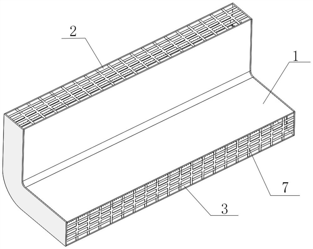
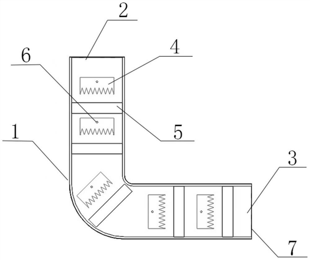
[0029] Such as figure 1 and figure 2 As shown, an air outlet structure of an air conditioner includes a casing 1 and at least one ion wind electrode arranged in the casing 1, and the two ends of the casing 1 are respectively provided with an air inlet 2 and an air outlet 2, and the ion wind electrode It includes a ring-shaped tip electrode 4 and a ring-shaped collector electrode 5 placed in parallel for the ion wind to pass through the middle. The end face of the ring-shaped tip electrode 4 is provided with serrations facing the direction of the wind. The tip electrode 4 is arranged on one side of the sawtooth, and the cross-sectional shape of the ring-shaped tip electrode 4 and the ring-shaped collector electrode 5 matches the cross-sectional shape of the housing 1 .

[0030] When a high voltage is applied between the tip electrode with a smaller radius of curvature and the collector electrode with a larger radius of curvature, a corona discharge occurs between the tip elec...

Embodiment 2

[0041] This embodiment is similar to Embodiment 1, except that, in this embodiment, the distance between the ring-shaped tip electrode 4 and the ring-shaped collector electrode 5 is 5mm, and the adjacent ring-shaped tip electrodes 4 The distance between the two sawtooth tips is 1cm, and the working voltage of the ion wind electrode is 5kV.

Embodiment 3

[0043] This embodiment is similar to Embodiment 1, except that, in this embodiment, the distance between the ring-shaped tip electrode 4 and the ring-shaped collector electrode 5 is 15 mm, and the adjacent ring-shaped tip electrodes 4 The distance between the two sawtooth tips is 3cm, and the working voltage of the ion wind electrode is 15kV.


PUM


Abstract

The invention discloses an ion wind generating device. The ion wind generating device comprises a shell and at least one ion wind power electrode arranged in the shell, an air inlet and an air outlet are formed in the two ends of the shell respectively, the ion wind power electrode comprises an annular tip electrode and an annular collector electrode which are arranged in parallel and allow ion wind to pass through the middle, sawteeth facing the air outlet direction are arranged on the end face of the annular tip electrode, the annular collector electrode is arranged on one side, provided with the sawteeth, of the annular tip electrode, and the section shape of the annular tip electrode and the section shape of the annular collector electrode are matched with the section shape of the shell. According to the ion wind generating device, the tip electrode and the collector electrode are annular, and the wind resistance is small when the generated ion wind passes through the electrodes, so that the situation that the generated ionic wind is too small in wind speed and wind quantity is avoided.

Description

technical field [0001] The present invention relates to the technical field of ion wind, and more specifically, to an ion wind generating device. Background technique [0002] Ion wind technology is a wind technology based on the corona effect. Its working principle is that the ion wind is generated in the corona discharge process of the uneven electric field. When the voltage between the collectors is high enough, a corona discharge phenomenon occurs inside the ion wind generator, and the ions generated by the corona effect are accelerated under the action of the electric field and collide with neutral molecules in the air to exchange momentum and energy, forming an orientation Sporty ionic wind. [0003] The Chinese patent document whose publication number is CN107872009B discloses an ion wind generating device and an air-conditioning indoor unit. The ion wind generating device includes at least one discharge module, each discharge module includes a housing, a mesh elect...

Claims


Application Information

Patent Timeline
Patent Type & Authority Applications(China)
IPC IPC(8): F24F8/192F24F8/30F24F13/20F24F13/24
CPCF24F8/30F24F8/192F24F13/24F24F13/20
Inventor 王长宏蔡坚锋罗思一曾志颢
Owner GUANGDONG UNIV OF TECH
Why Eureka
Eureka Blog
Learn More