
Tail reduction receiver and heavy duty tail reducer

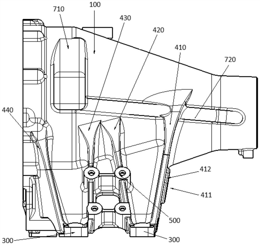
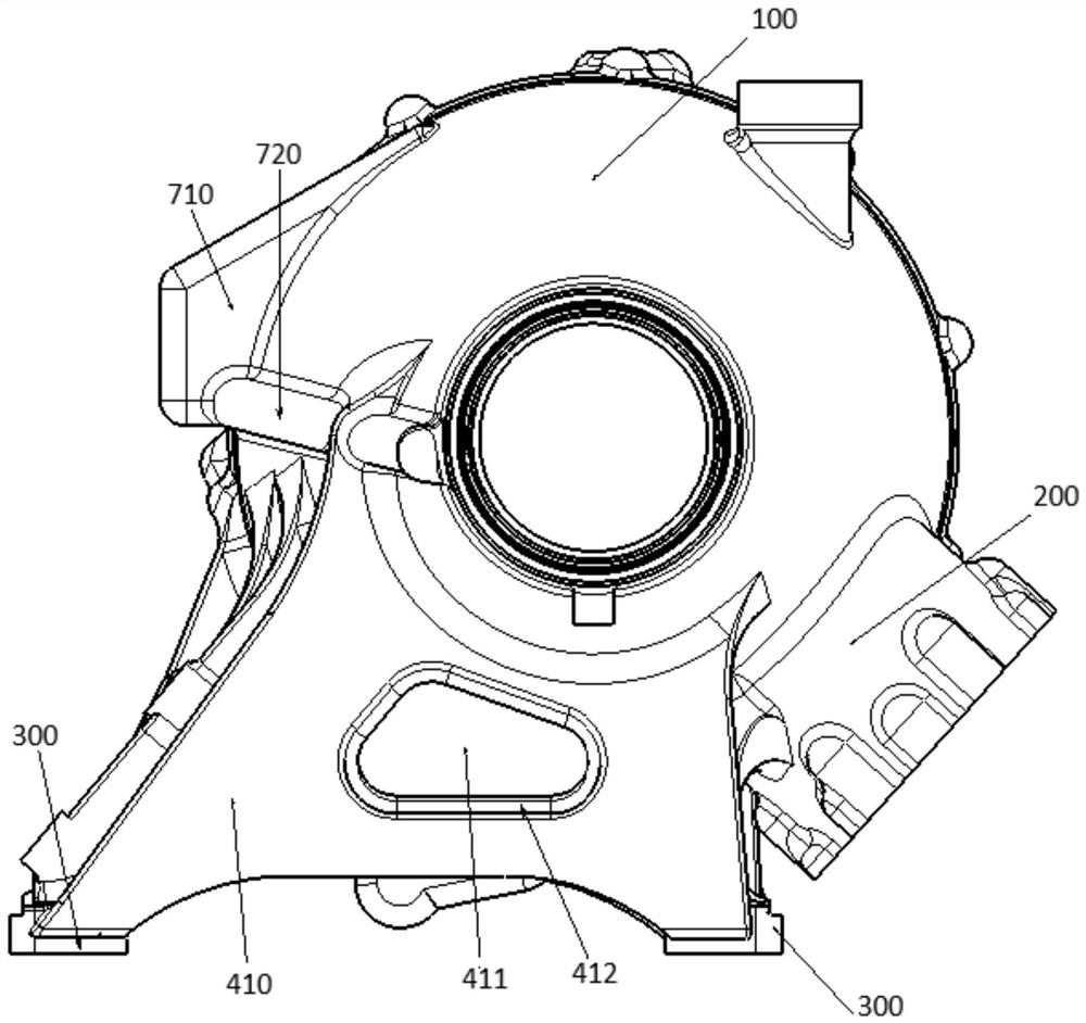
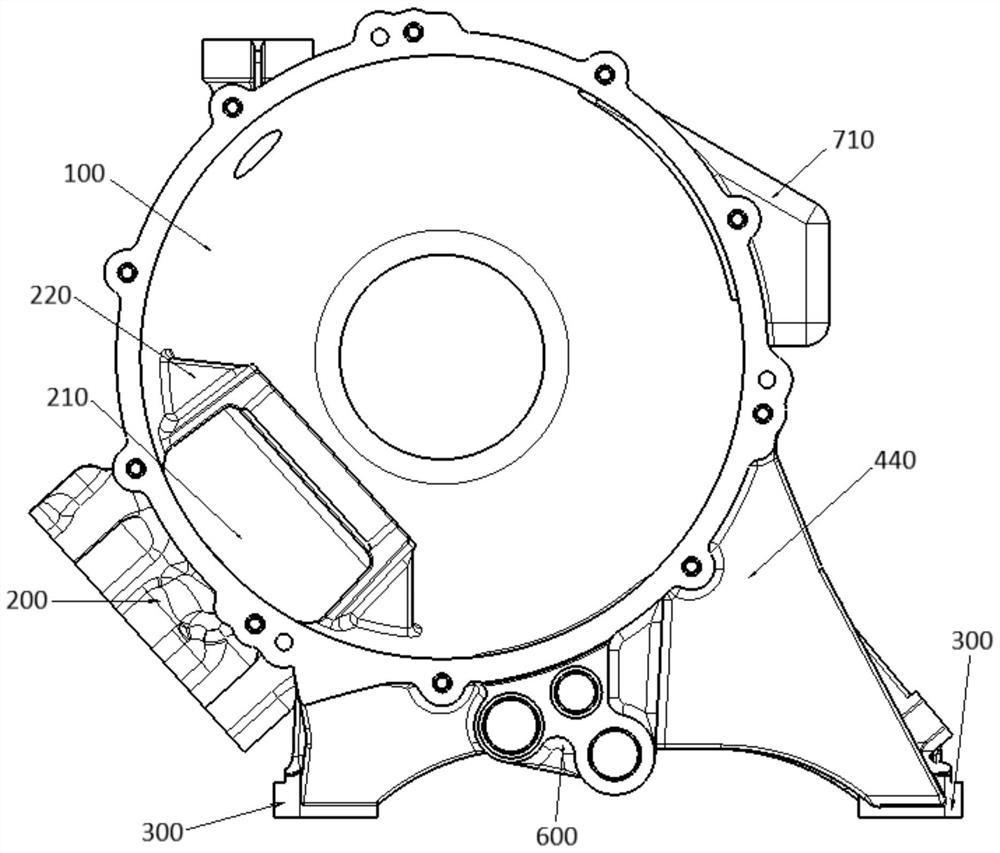
A technology for reducing the casing and the casing of the tail, which is applied in the directions of rotorcraft, motor vehicles, aircraft, etc., can solve the problems of complex structure, heavy weight of the tail reducing casing, and difficult processing, so as to simplify the structure of the equipment and ensure the bearing capacity. Strength, the effect of reducing the weight of the equipment

Active Publication Date: 2022-04-05
AECC HUNAN AVIATION POWERPLANT RES INST
View PDF7 Cites 0 Cited by
  • Summary
  • Abstract
  • Description
  • Claims
  • Application Information

AI Technical Summary

Problems solved by technology

Therefore, the weight of the existing tail reducing casing and the tail reducing casing are heavy, complex in structure, difficult to process and short in life.
In addition, the reinforcing plate of the main load-bearing part of the existing tail reducer casing cannot be equipped with weight-reducing holes, or once the weight-reducing holes are installed, the bearing capacity of the load-bearing parts will be affected

Method used


Image

  • Tail reduction receiver and heavy duty tail reducer
  • Tail reduction receiver and heavy duty tail reducer
  • Tail reduction receiver and heavy duty tail reducer

Examples


Embodiment Construction

[0042] Typical embodiments embodying the features and advantages of the present invention will be described in detail in the following description. It should be understood that the present invention can have various changes in different embodiments without departing from the scope of the present invention, and that the description and drawings therein are illustrative in nature and not intended to limit the present invention. invention.

[0043] In the following description of various exemplary embodiments of the invention, reference is made to the accompanying drawings, which form a part hereof, and in which are shown by way of example different exemplary structures, systems, and embodiments in which aspects of the invention may be implemented and steps. It is to be understood that other specific arrangements of components, structures, exemplary devices, systems and steps may be utilized and structural and functional modifications may be made without departing from the scope...


PUM


Abstract

The invention provides a tail reducer casing and a heavy-duty tail reducer. The tail reducer receiver includes the tail reducer main receiver, the tail reducer input receiver and multiple pairs of mounting legs. Wherein, the tail reduction main casing and the tail reduction input casing are integrally structured, a part of the tail reduction input casing is located inside the tail reduction main casing, and at least a part of the tail reduction input casing is located inside the tail reduction main casing. Hollow structure. The tail reduction casing also includes a plurality of reinforcement plates, each reinforcement plate is arranged between the same side of the two mounting legs of the same pair and the bottom of the tail reduction main case, and a plurality of reinforcement plates of the tail reduction main case are provided with reducing Heavy holes, the outermost reinforcing plate is provided with special-shaped lightening holes. Through the above design, the present invention changes the existing independent design of the tail reduction main casing and the tail reduction input casing into an integrated design, which can simplify the structure of the equipment and reduce the weight of the equipment. Furthermore, the tail reduction casing proposed by the present invention can not only reduce the weight of the equipment but also ensure the load-bearing strength through the design of the weight reduction hole.

Description

technical field [0001] The invention relates to the technical field of helicopter reducers, in particular to a tail reduction casing and a heavy-duty tail reducer. Background technique [0002] The tail reducer casing is an important part of the tail reducer of the helicopter. The existing tail reduction casing mainly includes two parts, the tail reduction input casing and the tail reduction main casing. These two parts belong to two mutually independent casings, and the tail reduction input casing is all solid in its circumferential direction structure. Therefore, the weight of the existing tail reducing casing and the tail reducing casing are heavy, complex in structure, difficult to process and short in life. In addition, the reinforcing plate of the main load-bearing part of the existing tail reducer casing cannot be provided with a weight-reducing hole, or once the weight-reducing hole is provided, the bearing capacity of the load-bearing part will be affected. Cont...

Claims


Application Information

Patent Timeline
Patent Type & Authority Patents(China)
IPC IPC(8): B64C27/12B64D35/00
CPCB64C27/12B64D35/00
Inventor 陈江文楚炯陶海苏新生戴化郑生旭
Owner AECC HUNAN AVIATION POWERPLANT RES INST
Learn More