Turbine guide cooling blade

A technology for cooling blades and turbines, applied in the direction of blade support components, stators, engine components, etc., can solve the problems of large thermal stress, low utilization rate of cold air, poor uniformity of temperature distribution of blades, etc., and achieve small thermal stress and utilization rate of cold air High, even blade temperature distribution effect

Active Publication Date: 2020-08-04
AECC HUNAN AVIATION POWERPLANT RES INST
View PDF6 Cites 1 Cited by
  • Summary
  • Abstract
  • Description
  • Claims
  • Application Information

AI Technical Summary

Problems solved by technology

However, the existing guide vane blade regions, such as blade leading edge, blade midchord region, blade trailing edge and other regions, all adopt roughly the same cooling gas convection method, and there are poor uniformity of blade temperature distribution and thermal stress. Many problems with large size and low air-conditioning utilization

Method used


Image

  • Turbine guide cooling blade
  • Turbine guide cooling blade
  • Turbine guide cooling blade

Examples


Embodiment Construction

[0048] Typical embodiments embodying the features and advantages of the present invention will be described in detail in the following description. It should be understood that the present invention can have various changes in different embodiments, which do not depart from the scope of the present invention, and the descriptions and drawings therein are essentially for illustrative purposes, rather than limiting the present invention. invention.

[0049] In the following description of the different exemplary embodiments of the present invention, it is made with reference to the accompanying drawings, which form a part of the present invention, and therein are shown by way of example different exemplary structures and systems that can implement various aspects of the present invention. And steps. It should be understood that other specific solutions of components, structures, exemplary devices, systems, and steps may be used, and structural and functional modifications may be m...


PUM


Abstract

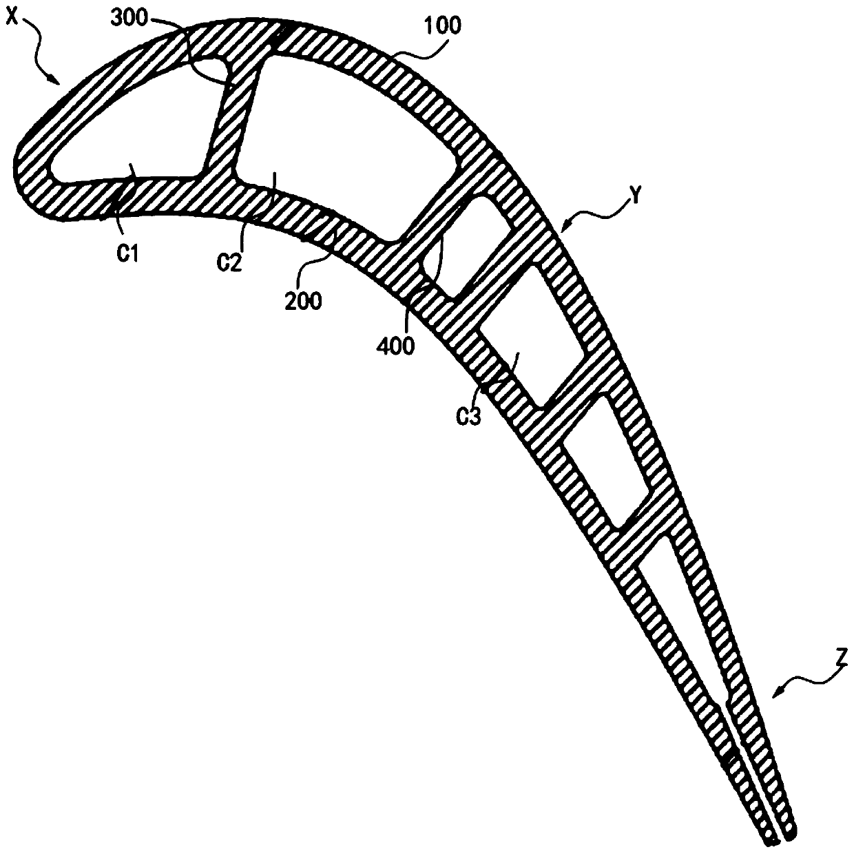
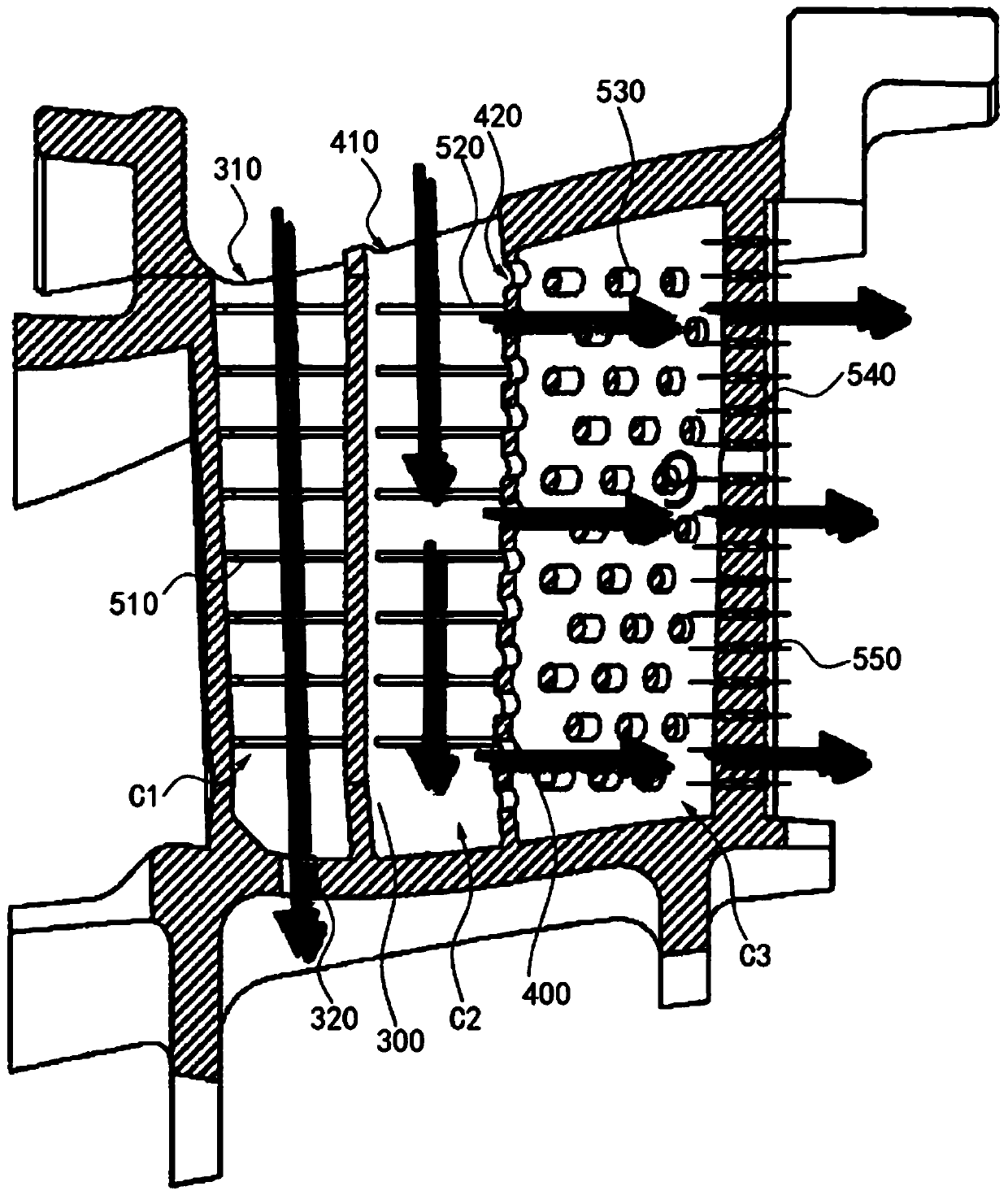
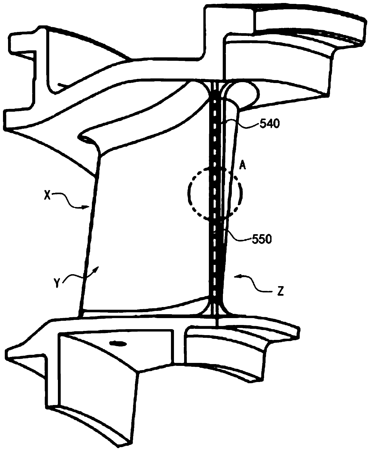
The invention provides a turbine guide cooling blade. The turbine guide cooling blade comprises a blade back and a blade basin, wherein a blade cavity is defined by the blade back and the blade basin,the turbine guide cooling blade further comprises a first partition plate and a second partition plate, the first partition plate and the second partition plate are connected between the blade back and the blade basin and sequentially arranged in the blade cavity in the radial direction, the blade cavity is divided into a first cavity, a second cavity and a third cavity which are sequentially arranged in the axial direction through the first partition plate and the second partition plate, the turbine guide cooling blade is provided with a first air inlet, a second air inlet and a first air outlet, the first air inlet and the first air outlet communicate with the radial upper side and the radial lower side of the first cavity respectively, the second air inlet communicates with the radialupper side of the second cavity, a plurality of through holes are formed in the second partition plate, the second cavity communicates with the third cavity through the plurality of through holes, a plurality of impact holes are formed in the blade tail edge of the turbine guide cooling blade, and the third cavity communicates with the outside of the turbine guide cooling blade through the impactholes.

Description

Technical field [0001] The invention relates to the technical field of aeroengines, in particular to a turbine guide cooling blade. Background technique [0002] The guide blades directly face the scouring of the incoming high-temperature gas. After the high-temperature gas passes through the turbine guide blades, the airflow direction changes and the temperature decreases, which improves the environment for the expansion of the rotor blades to perform work. Therefore, the guide blades are an indispensable part of the gas turbine stage. However, the blade areas of the existing guide blades, such as the leading edge of the blade, the mid-chord area of ​​the blade, and the trailing edge of the blade, all adopt roughly the same cooling gas convection method, and there are poor uniformity of blade temperature distribution and thermal stress. Larger and lower air-conditioning utilization rate. Summary of the invention [0003] A main purpose of the present invention is to overcome at ...

Claims


Application Information

Patent Timeline
Patent Type & Authority Applications(China)
IPC IPC(8): F01D5/18F01D9/02
CPCF01D5/18F01D9/02Y02T50/60
Inventor 赵兰芳陈文彬贺宜红
Owner AECC HUNAN AVIATION POWERPLANT RES INST
Why Eureka
Try Eureka