Drop-down detector and detection system
A detection system and detector technology, used in instruments, measuring devices, scientific instruments, etc., can solve the problems of data transmission distance and weak wind resistance of detectors, and achieve the effect of improving wind resistance and increasing data transmission distance.
- Summary
- Abstract
- Description
- Claims
- Application Information
AI Technical Summary
Problems solved by technology
Method used
Image
Examples
Embodiment 1
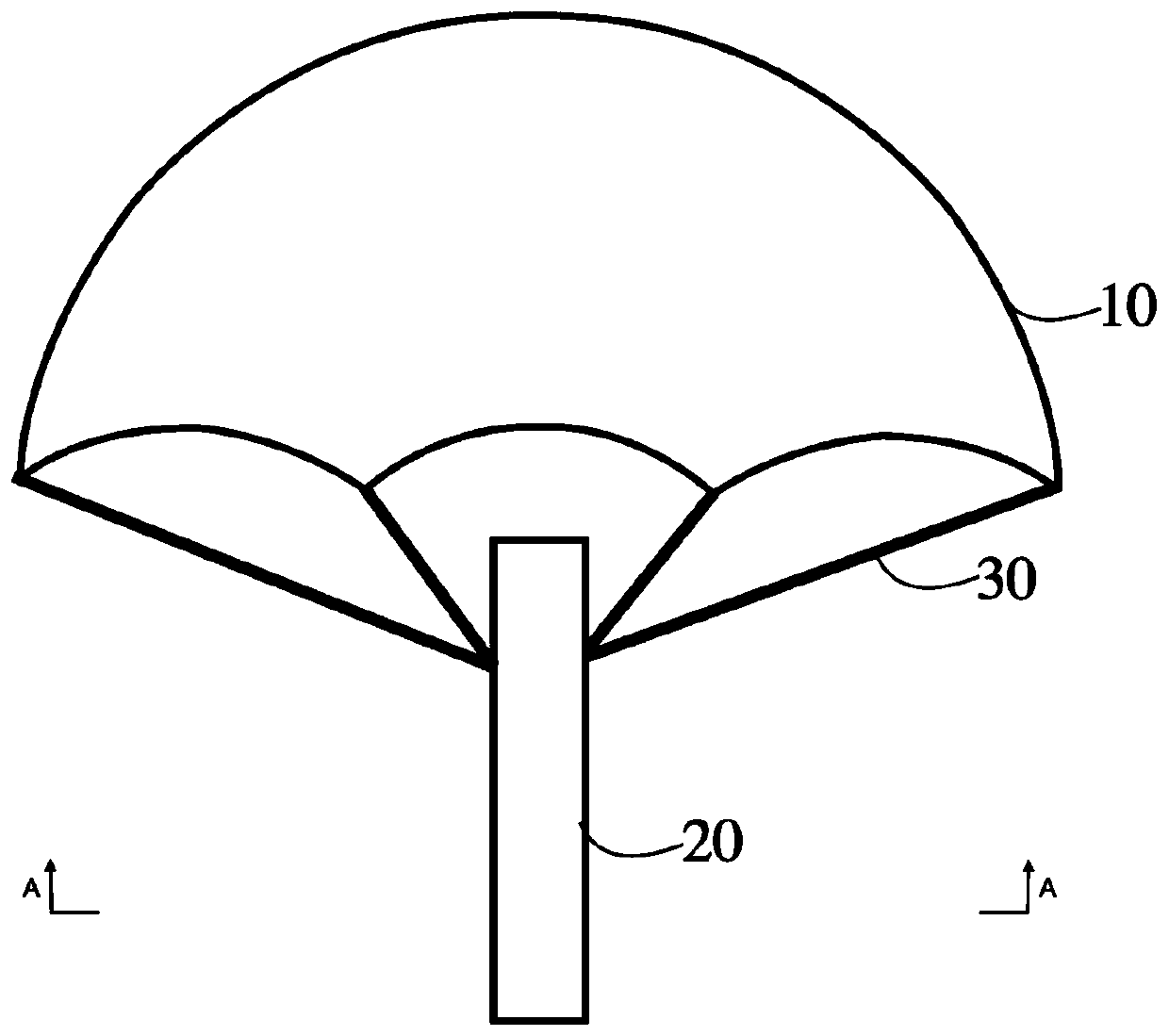
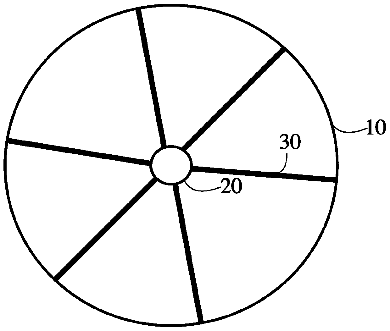
[0034] figure 2 is a schematic diagram of a drop detector according to Embodiment 1 of the present invention; image 3 yes figure 2 The schematic diagram of the drop detector shown in the A-A direction, Figure 4A yes figure 2 The schematic diagram of the drop detector shown in the breeze state; Figure 4B yes figure 2 A schematic diagram of the drop detector shown in strong wind conditions. refer to figure 2 , image 3 , Figure 4A , Figure 4B , The drop-type detector described in this embodiment includes a first umbrella surface 10, a main body 20, and a plurality of communication antennas 30, which are used to collect meteorological information in complex and harsh environments such as typhoons. Each will be described below.
[0035] The first umbrella surface 10 is a parachute umbrella surface, which can be circular when unfolded, and is used to drive the detector to float down.
[0036] The main body 20 is in the shape of a cylinder, and a weather informa...
Embodiment 2
[0062] Figure 6 is a schematic diagram of the drop detector according to Embodiment 2 of the present invention. refer to Figure 6 , the drop-type detector of the present embodiment is used for collecting meteorological information in complex and harsh environments such as typhoons, and it includes the first umbrella surface 10, the main body 20, and the plurality of communication antennas 30 described in Embodiment 1, as well as A second canopy 40 is included.
[0063] The second umbrella surface 40 is positioned at the lower side of the plurality of communication antennas 30 relative to the first umbrella surface 10, that is, the first umbrella surface 10 is positioned at the upper side of the plurality of communication antennas 30, and the second umbrella surface 40 is positioned at the bottom of the plurality of communication antennas 30. underside. One edge of the second umbrella surface 40 is connected with the outer periphery of the main body portion 20, and the oth...
Embodiment 3
[0066] Figure 7 is a schematic diagram of the drop detection system according to Embodiment 3 of the present invention. Such as Figure 7 As shown, the drop detection system includes an airborne receiving device 110 mounted on an aircraft, and a plurality of drop detection instruments 120 described in Embodiment 1 or 2 above that are placed at different positions.
[0067] The drop-type detection system described in this embodiment can obtain meteorological information at different levels and heights through multiple drop-type detectors 120, so as to obtain meteorological information from multiple dimensions and realize continuous and fine detection of large-scale gridding .
[0068] Before launching, a plurality of drop-type detectors 120 can be respectively accommodated in their respective casings and loaded in the release bin of the aircraft, wherein, when stored in the casings of the detectors, the plurality of communication antennas are fixed to the The axis of the ma...
PUM
| Property | Measurement | Unit |
|---|---|---|
| Diameter | aaaaa | aaaaa |
| Length | aaaaa | aaaaa |
Abstract
Description
Claims
Application Information
 - R&D
- Intellectual Property
- Life Sciences
- Materials
- Tech Scout
- Unparalleled Data Quality
- Higher Quality Content
- 60% Fewer Hallucinations
Browse by: Latest US Patents, China's latest patents, Technical Efficacy Thesaurus, Application Domain, Technology Topic, Popular Technical Reports.
© 2025 PatSnap. All rights reserved.Legal|Privacy policy|Modern Slavery Act Transparency Statement|Sitemap|About US| Contact US: help@patsnap.com


