Debugging method of imaging system

A debugging method and imaging system technology, applied in the direction of image communication, television, electrical components, etc., can solve the problems of difficult valid data and invalid data, distinction, random image data, etc., to achieve the effect of accurate inspection

Active Publication Date: 2020-08-04
CHANGCHUN INST OF OPTICS FINE MECHANICS & PHYSICS CHINESE ACAD OF SCI
View PDF10 Cites 5 Cited by
  • Summary
  • Abstract
  • Description
  • Claims
  • Application Information

AI Technical Summary

Problems solved by technology

[0003] The present invention provides a debugging method for an imaging system in order to solve the problem that the existing imaging system has no invalid da...

Method used


Image

  • Debugging method of imaging system
  • Debugging method of imaging system
  • Debugging method of imaging system

Examples


specific Embodiment approach 1

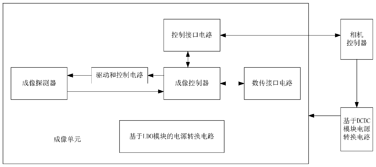
[0027] Specific implementation mode 1. Combination Figure 1 to Figure 3 Describe this embodiment, a debugging method of an imaging system; including an imaging control system, the imaging control system includes a camera controller, a DCDC module power conversion circuit and an imaging unit; the imaging unit includes a power conversion circuit based on an LDO module, Imaging detector, drive and control circuit, imaging controller, data transmission interface circuit and control interface circuit. The power conversion circuit of the LDO module provides power supply for each part of the imaging unit; the power conversion circuit of the DCDC module supplies power to the imaging unit, and whether the power supply is controlled by the camera controller. The control communication signal output by the controller is sent to the imaging controller through the control interface circuit; the driving and control signal generated by the imaging controller is sent to the imaging detector a...


PUM


Abstract

The invention discloses a debugging method of an imaging system. The invention relates to the technical field of aerospace application imaging. The problem that effective data and invalid data are difficult to distinguish due to the fact that invalid data zero clearing operation does not exist in a detector and image data output in an invalid data stage are random in an existing imaging system issolved, and for the risk that a refreshing chip connected with an FPGA is not powered on and has latent conduction, unused pins are set to be at a low level; the pins which need to be connected are connected with resistors in series, and possible interference is filtered out by using capacitors; and the influence of dive-through can be reduced, and meanwhile, the application reliability is not reduced. Aiming at possible image blurring caused by temperature change of the detector, a secondary training operation method is provided, and image blurring is avoided. For the situation that no invalid data zero clearing operation exists in the detector, image data output in the invalid data stage is random, and valid data and invalid data are difficult to distinguish; pixel-by-pixel lightening and extinguishing are adopted, so that effective data positions can be accurately checked.

Description

technical field [0001] The invention relates to the technical field of aerospace application imaging, in particular to a debugging method for an imaging system. Background technique [0002] For multi-working mode applications, when the refresh chip is not powered on, but the FPGA and the bus driver connected to the refresh chip are powered on, the FPGA and the bus driver will feed power to the refresh chip through the connected IO. If the voltage of the refresh chip rises to the threshold voltage, it may start to work and control the configuration data flow inside the FPGA, causing the FPGA to fail to work properly. If the temperature of the detector changes in a large range relative to the starting training time, the phase of the output serial data will change greatly, and a sampling metastable state may occur, resulting in some channel images becoming blurred. Since there is no invalid data clearing operation inside the detector, the output image data in the invalid data...

Claims


Application Information

Patent Timeline
IPC IPC(8): H04N17/00
CPCH04N17/002
Inventor 余达刘金国徐东梅贵张凯傅瑶赵宇宸
Owner CHANGCHUN INST OF OPTICS FINE MECHANICS & PHYSICS CHINESE ACAD OF SCI
Why Eureka
Try Eureka